Power distribution panel

a power distribution panel and power distribution technology, applied in the direction of electrical apparatus, substation/switching arrangement details, coupling device connections, etc., can solve the problem that the user cannot flexibly design the electrical stability of the load side, and achieve the effect of convenient power distribution, flexible design of electrical stability, and secured electrical stability of the incoming power

Inactive Publication Date: 2008-03-04
BMT LIMITED
View PDF13 Cites 14 Cited by
  • Summary
  • Abstract
  • Description
  • Claims
  • Application Information

AI Technical Summary

Benefits of technology

[0012]As mentioned above, since the present invention has an input terminal to which the incoming power source is connected, and a plurality of output terminals for distributing the power to the load sides, convenient power distribution from the source to the load sides can be accomplished.
[0013]In addition, since the stabilizer or circuit breaker of the incoming power is connected to the input terminal through the connecting means, the electrical stability of the incoming power can be secured; since the load sides are connected to the output terminals, the input and output of the whole load sides can be controlled by the stabilizer or circuit breaker connected to the input terminal.
[0014]In addition, since various stabilizers or circuit breakers are selectively connected to the respective output terminals, user can flexibly design the electrical stability, if necessary.

Problems solved by technology

Additionally, a single stabilizer or circuit breaker cannot control the input and output of the whole load sides, and further a user cannot flexibly design the electrical stability for the load sides, if necessary.

Method used


Image

  • Power distribution panel
  • Power distribution panel
  • Power distribution panel

Examples


Embodiment Construction

[0020]Hereinafter, preferred embodiments of the present invention will be described in detail with reference to the attached drawings. In description, if the detailed description about the related prior arts and construction thereof is considered that it confuses the subject matter of the invention, the description will be omitted. The following terminologies are defined by considering the functions in the present invention, which are subject to change in accordance with the intention of users or operators, or the conventions. Therefore, the definition of the terminologies should be construed based upon the whole contents of the specification describing a power distribution panel.

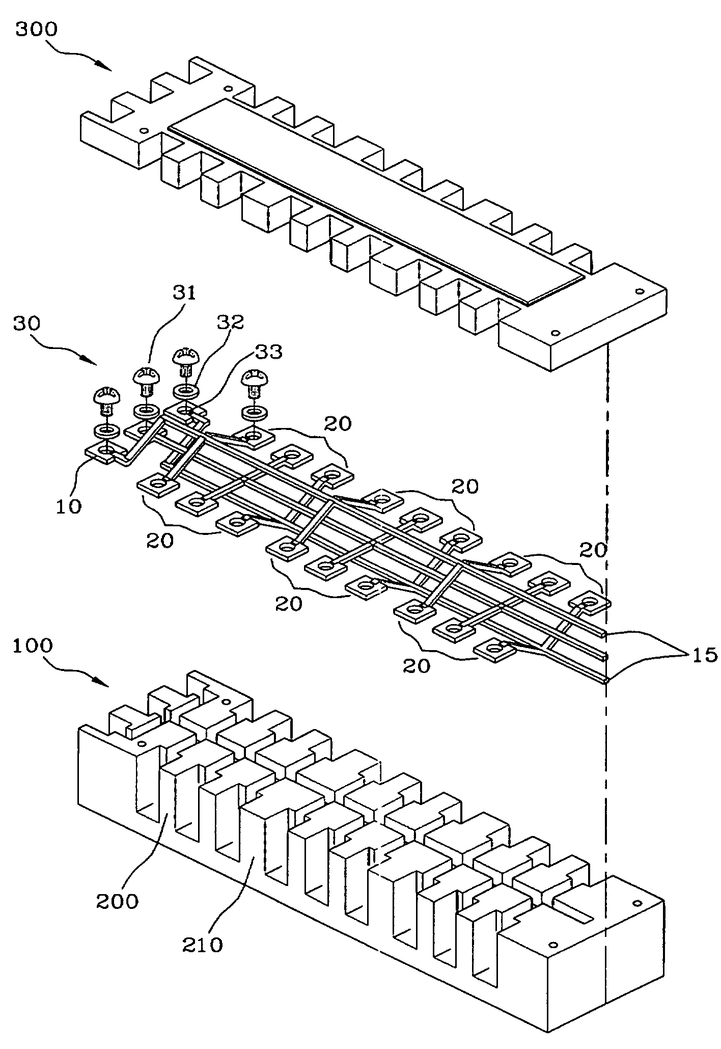
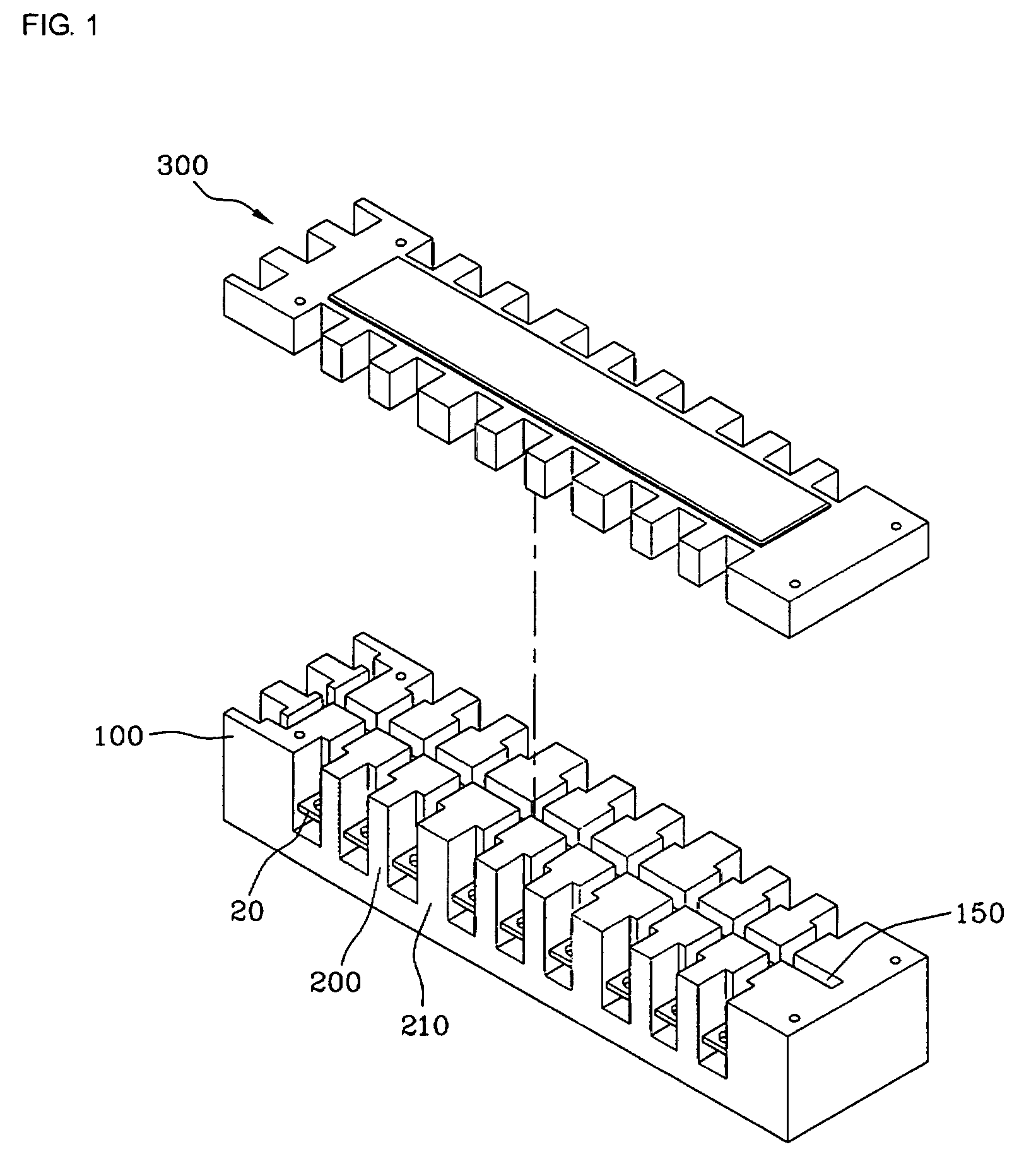
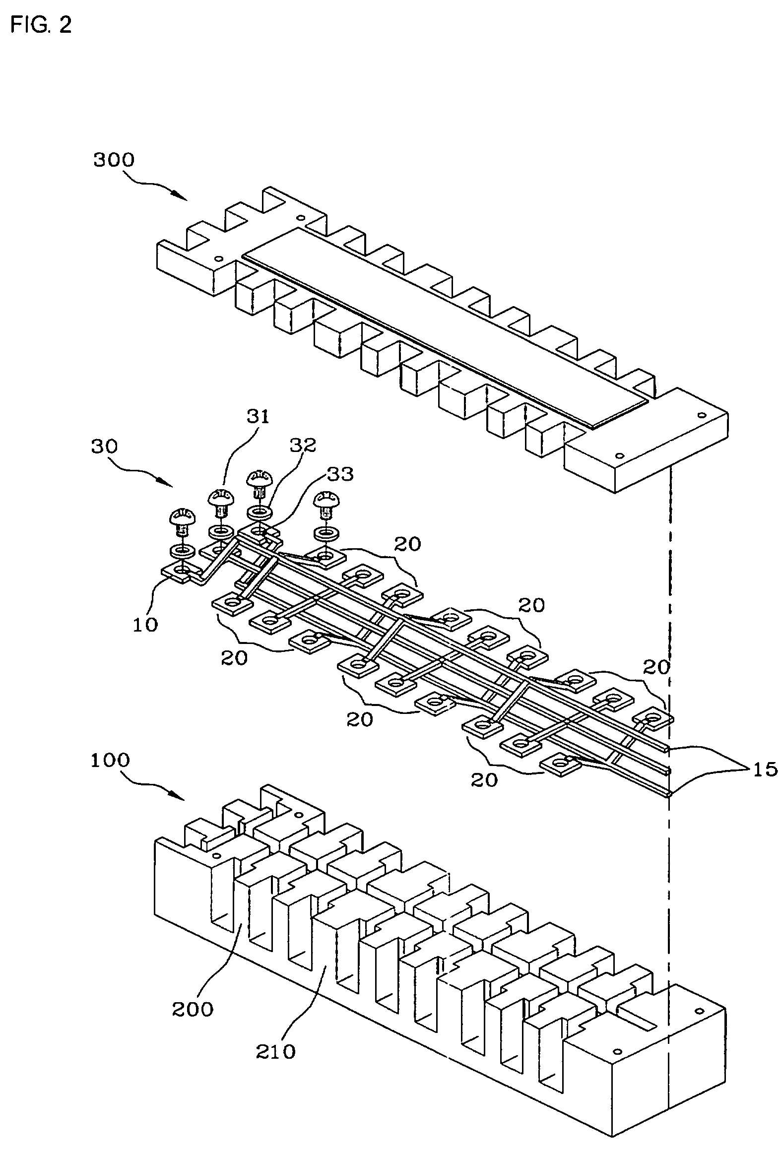
[0021]FIGS. 1 and 2 are respectively a schematic diagram and an exploded perspective view showing a power distribution panel according to one embodiment of the present invention, FIG. 3 is a schematic diagram of an output terminal of a power distribution panel according to another embodiment of the present ...


PUM


Abstract

The present invention relates to a power distribution panel in which a plurality of loads is connected to an incoming power source. The power distribution panel comprises an input terminal connecting with an incoming power line; a common line extending from the input terminal; a plurality of introduction lines furcating from the common line in parallel; connecting means connecting with different load sides, such as a circuit breaker; and a terminal body comprising a central slot in which the common line is built, a plurality of side slots in which the respective introduction lines are built, an insulation block projectingly formed on the sides of the terminal body, and an identification block for identifying the output terminals of unit source out of the plurality of parallel-connected output terminals. According to the present invention, the input power can be distributed to the load sides conveniently, and a user can flexibly design the electrical stability, if necessary.

Description

TECHNICAL FIELD[0001]The present invention relates to a power distribution panel, and more particularly to such a power distribution panel which comprises an input terminal including a tapped hole, a screw engaged with the tapped hole, and a washer, so as to connect with an incoming power line; a common line extending from the input terminal; a plurality of introduction lines furcating from the common line in parallel; connecting means including a plurality of output terminals which form end points of the introduction lines so as to connect with different load sides, such as a circuit breaker; and a terminal body comprising a central slot in which the common line is built; a plurality of side slots in which the respective introduction lines are built; an insulation block projectingly formed on the sides of the terminal body, so that it guides the introduction lines to the output terminals and insulates the respective introduction lines; and an identification block for identifying th...

Claims


Application Information

Patent Timeline
Patent Type & Authority Patents(United States)
IPC IPC(8): H01R9/22H01R9/24H01R25/00H01R31/02H02B1/056
CPCH01R9/2475H01R25/00H02B1/056H01R9/226H01R9/22H01R31/02
Inventor YOON, JONG-CHAN
Owner BMT LIMITED
Why Eureka
Try Eureka