
Combined slit/pinhole collimator method and system

a collimator and slit technology, applied in the field of noninvasive imaging, can solve the problems of large and expensive positioning system, inability to provide the desired resolution and sensitivity, and current system that does not provide the desired positional resolution,

Active Publication Date: 2008-03-04
GENERAL ELECTRIC CO
View PDF27 Cites 31 Cited by
  • Summary
  • Abstract
  • Description
  • Claims
  • Application Information

AI Technical Summary

Benefits of technology

The present invention provides a collimator assembly and an imaging system that can detect gamma rays emanating from a field of view. The collimator assembly includes an inner combined collimator and an outer collimator with slit apertures and pinhole apertures arranged to define a plurality of apertures through the collimator assembly. The detector array can generate signals in response to the detected gamma rays. The technical effect of this invention is to improve the accuracy and sensitivity of imaging systems that use collimators to detect gamma rays.

Problems solved by technology

The technical problem addressed in this patent is to provide an improved non-invasive imaging system with better positional resolution and sensitivity, while also reducing examination times and simplifying the positioning system.

Method used


Image

  • Combined slit/pinhole collimator method and system
  • Combined slit/pinhole collimator method and system
  • Combined slit/pinhole collimator method and system

Examples


Embodiment Construction

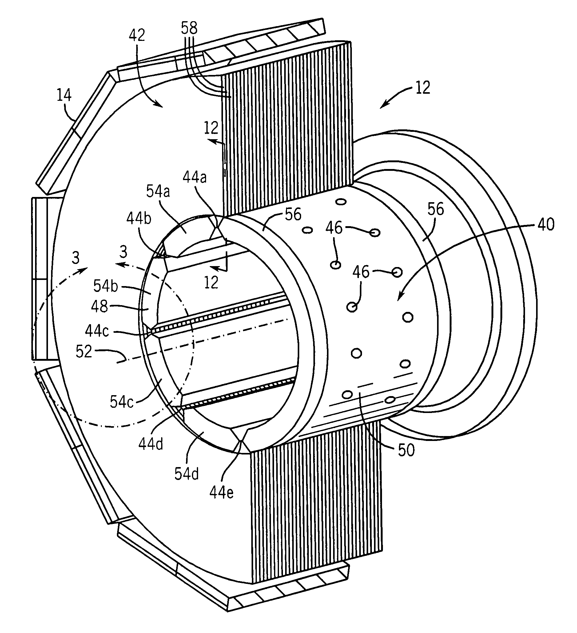
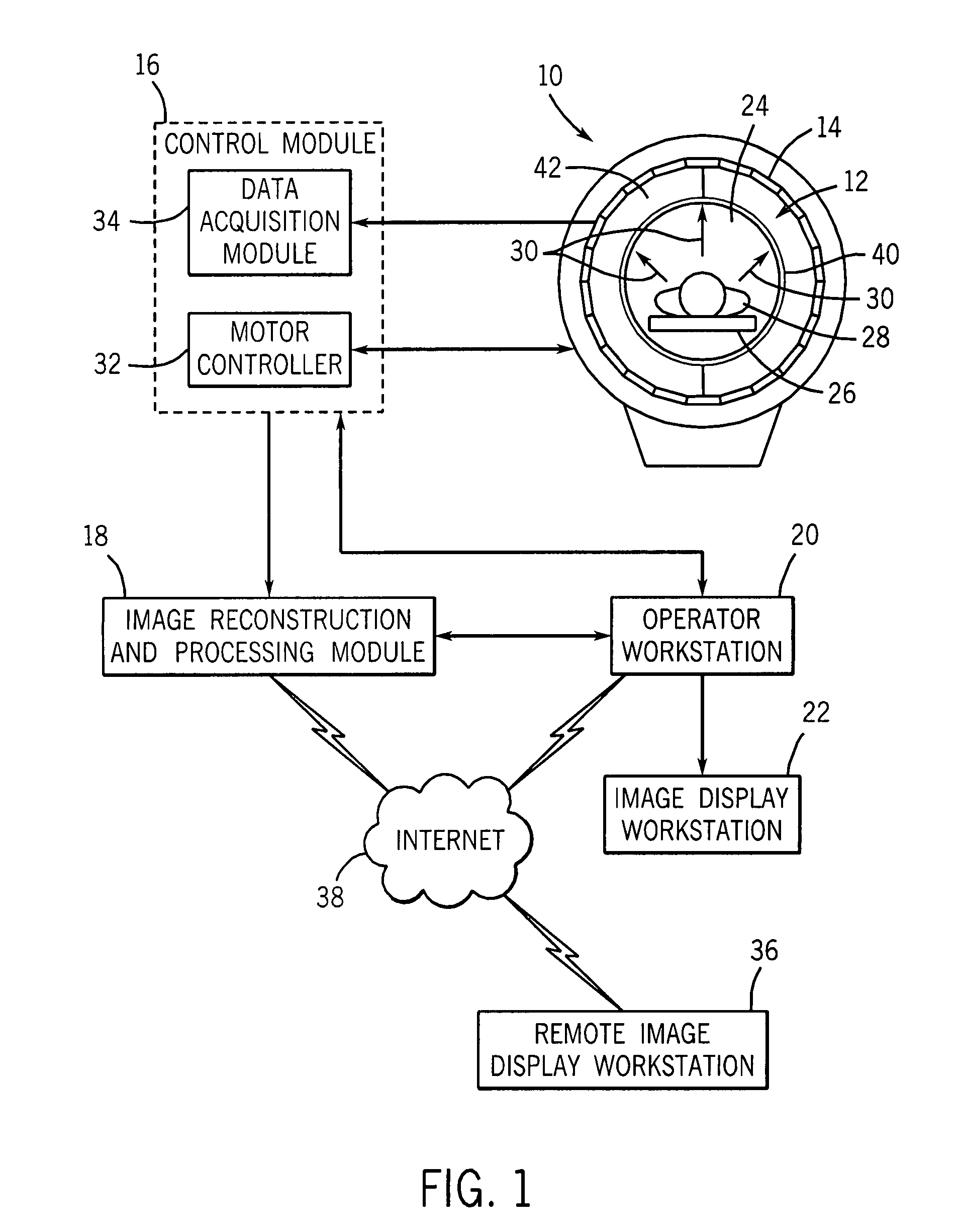
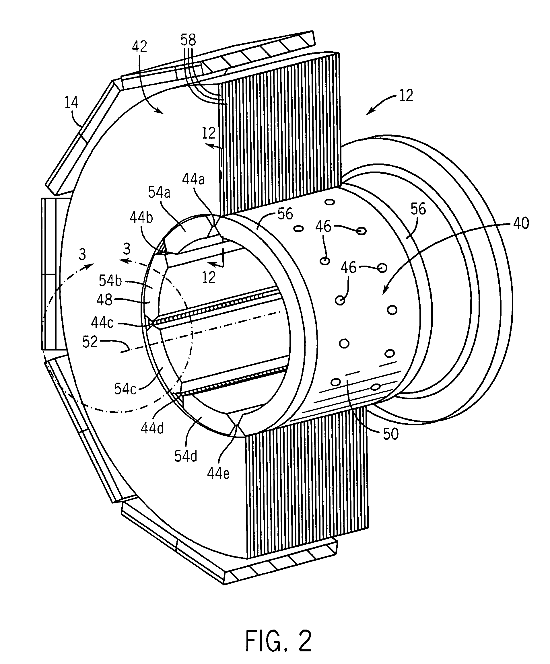
[0027]FIG. 1 illustrates an exemplary SPECT system 10 for acquiring and processing image data in accordance with exemplary embodiments of the present technique. In the illustrated embodiment, SPECT system 10 includes a collimator assembly 12 and a detector assembly 14. The SPECT system 10 also includes a control module 16, an image reconstruction and processing module 18, an operator workstation 20, and an image display workstation 22. Each of the aforementioned components will be discussed in greater detail in the sections that follow.

[0028]SPECT system 10 also includes a field of view 24 into which a subject support 26 (e.g. a table) may be positioned for supporting a subject 28 (e.g., a human patient, a small animal, a plant, a porous object, etc.) in a generally stationary position for scanning. Alternatively, the subject support 26 may be stationary, while the SPECT system 10 may be positioned around the subject 28 for scanning. Those of ordinary skill in the art will appreciat...


PUM


Abstract

Collimator assemblies that include an inner combined collimator and an outer collimator are provided. The inner combined collimator includes a first portion having one or more slit apertures therein, and a second portion having one or more pinhole apertures therein. The outer collimator includes one or more septa spaced on a side of the first portion of the inner combined collimator. The slit apertures of the inner combined collimator and the septa of the outer collimator are arranged to define a plurality of apertures through the collimator assembly. Imaging systems that include the collimator assemblies and a detector assembly are also provided. The detector assembly may be configured to detect gamma rays emanating from a field of view that pass through apertures defined by the collimator assembly and to generate one or more signals in response to the detected gamma rays. Methods of imaging a field view using the collimating assembly are also provided.

Description


Claims


Application Information

Patent Timeline
Owner GENERAL ELECTRIC CO
Learn More