Apparatus and method of image synthesization

a technology of image and synthesizer, applied in the field of apparatus and method of synthesizing spotlighted images, can solve the problems of complicated, complicated, and formation of headlight pattern in a far away configuration, and achieve the effect of avoiding the formation of shadows, avoiding shadows, and avoiding shadows

Inactive Publication Date: 2000-08-08
BANDAI NAMCO ENTERTAINMENT INC
View PDF7 Cites 92 Cited by
  • Summary
  • Abstract
  • Description
  • Claims
  • Application Information

AI Technical Summary

Problems solved by technology

When the headlight beams are projected against the wall as described, however, a problem may be raised in that the headlight pattern is formed in a configuration far away from the reality.
However, since the two light sources cannot be considered to be at the infinite points in such a case, the light beams from the light sources cannot be made as parallel rays.
Thus, the shading operation based on these l

Method used


Image

  • Apparatus and method of image synthesization
  • Apparatus and method of image synthesization
  • Apparatus and method of image synthesization

Examples


first embodiment

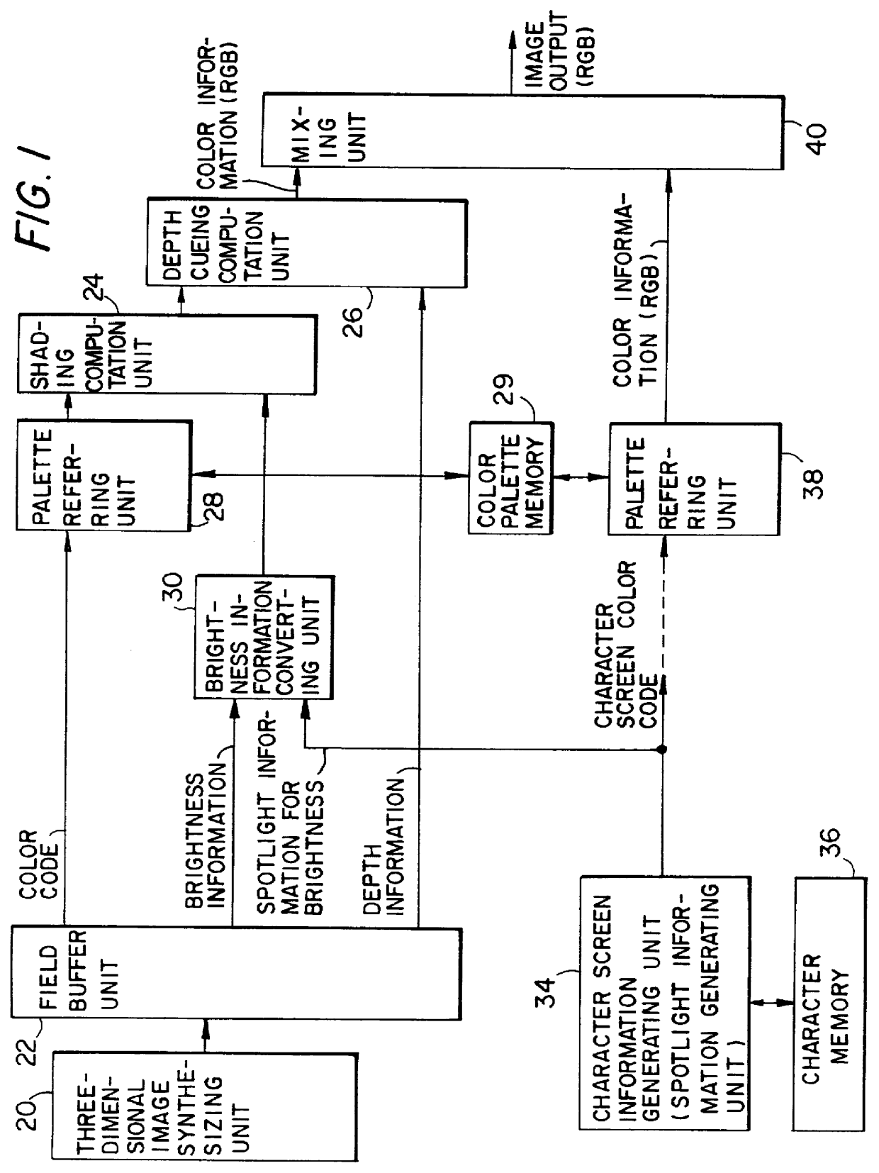
FIG. 1 is a block diagram of the present invention. Referring to FIG. 1, the first embodiment comprises a three-dimensional image synthesizing unit 20, a field buffer unit 22, a shading computation unit 24, a depth cueing computation unit 26, a palette referring unit 28, a color palette memory 29, a brightness information converting unit 30, a character screen information generating unit (spotlight information generating unit) 34, a character memory 36, a palette referring unit 38 and a mixing unit 40.

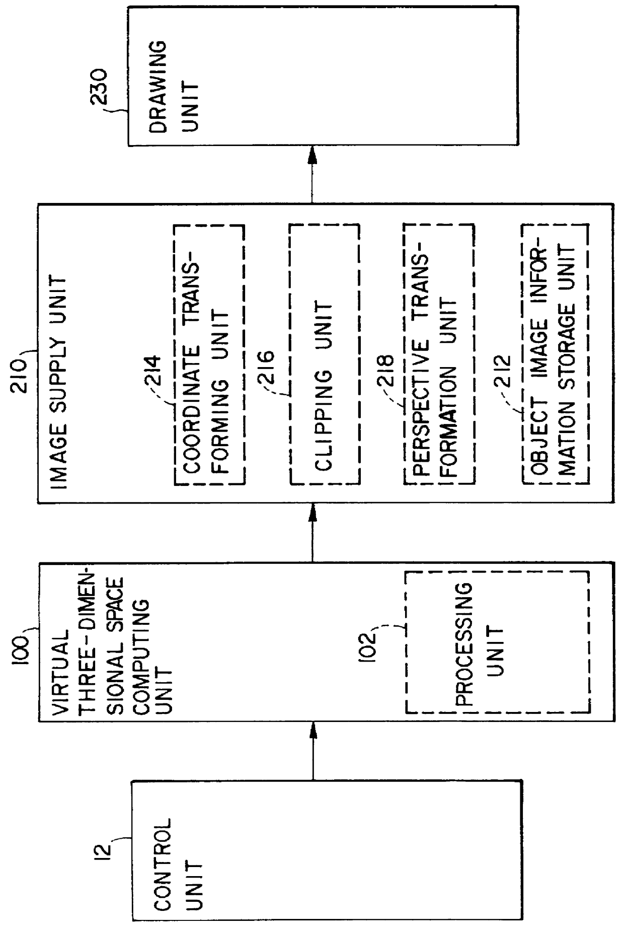
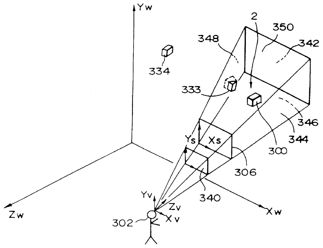
The three-dimensional image synthesizing unit 20 synthesizes a two-dimensional image after perspective transformation at a given viewpoint in a line-of-sight direction within a virtual three-dimensional space in which a plurality of objects are disposed. FIG. 2 shows the block diagram thereof.

In FIG. 2, a control unit 12 may include a steering wheel, accelerator and others if the image synthesizing apparatus is applied to a racing car game. These control instruments can be actuated by ...

second embodiment

FIG. 8 is a block diagram of a second embodiment according to the present invention. As can be seen from a comparison between FIGS. 1 and 8, the second embodiment is different from the first embodiment in that a depth information converting unit 32 is newly provided and that the character screen information generating unit 34 outputs spotlight information for brightness and depth which are in turn inputted into the brightness and depth information converting units 30, 32, respectively. The brightness and depth information converted by the brightness and depth information converting units 30, 32 are respectively inputted into the shading and depth cueing computation units 24, 26 wherein the shading and depth cueing computations are executed based on these inputted information.

The depth information converting unit 32 uses the spotlight information for depth from the character screen information generating unit 34 which is also serving as the spotlight information generating unit to pr...

third embodiment

FIG. 9 is a block diagram of a third embodiment according to the present invention. As can be seen from a comparison of FIG. 1 with FIG. 9, the third embodiment is characterized by that it comprises a depth information converting unit 32 in place of the brightness information converting unit 30. The character screen information generating unit 34 generates the spotlight information for depth rather than the spotlight information for brightness. The spotlight information for depth is inputted into the depth information converting unit 32. The depth information converting unit 32 uses the spotlight information for depth to convert depth information from the field buffer unit 22, the result being then outputted toward the depth cueing computation unit 26. The brightness information outputted from the field buffer unit 22 is inputted into the shading computation unit 24 without being subjected to the conversion by the brightness information converting unit.

According to the third embodim...


PUM


Abstract

A character screen information generating unit (34) has a function also serving as a spotlight information generating unit and outputs spotlight information for brightness toward a brightness information converting unit (30). The brightness information converting unit (30) uses this spotlight information for brightness to convert brightness information. A shading computation unit (24) uses the converted brightness information and color information of an object to determine color information to be displayed on a display at each pixel. A depth cueing computation unit (26) uses depth information to make a depth cueing computation relative to the determined color information. Thus, a pattern such as headlight can be displayed in the form of spotlight. Further, such a spotlight display can reflect by the depth information. There may further be provided a depth information converting unit for converting the depth information by the use of spotlight information for depth.

Description

1. Field of the InventionThe present invention relates to an apparatus and method of synthesizing a spotlighted image.2. Description of the Prior ArtVarious types of image synthesizing systems are known which may be used in three-dimensional games, simulators for controlling airplanes and other vehicles and others. In such image synthesizing systems, image information relating to such a three-dimensional object 300 as shown in FIG. 13A has been stored therein. The three-dimensional object 300 represents a scenery or other expression which can be seen by a player (observer) 302 through a screen 306. The image information of the three-dimensional object 300 is perspectively transformed onto the screen 306 to form an image (projected image) 308. When the player 302 rotates or translates a moving body on which the player 302 is assumed to get through a control panel 304, the player 302 or the moving body will be changed in position and direction. Depending on such changes, a computation...

Claims


Application Information

Patent Timeline
IPC IPC(8): G06T15/50G06T15/80
CPCG06T15/50G06T15/80A63F2300/66A63F2300/8017
Inventor MIURA, KATSUHIROYOKOTA, TAKASHITAKEDA, MASAKIKONISHI, KUNIYUKI
Owner BANDAI NAMCO ENTERTAINMENT INC
Why Eureka
Try Eureka