Electric optical distance wavelength meter

a wavelength meter and optical technology, applied in the field of electric optical distance wavelength meter, can solve the problem of requiring more time than desired to measure the distance, and achieve the effect of remarkably reducing the time required for measuring the distance and highly precise measuremen

Inactive Publication Date: 2008-03-04
SOKKOIA COMPANY LIMITED
View PDF8 Cites 53 Cited by
  • Summary
  • Abstract
  • Description
  • Claims
  • Application Information

AI Technical Summary

Benefits of technology

[0009]The present invention has been accomplished in view of the problems described above. It is an object of the present invention to provide an electric optical distance wavelength meter detecting the time when the switching is completed and shortening the time required for distance measurement by immediately starting the distance measurement when measurement light and reference light are switched by a light path switching device.
[0025]Furthermore, the electric optical distance wavelength meter according to the eighth aspect of the present invention detects the change in scattering of the amplitude of the light receiving signal or the calculated distance, or the scattering of amplitude and the distance to determine the switching completion of the light path switching device, and starts the usual distance measurement. Thereby, the time required for measuring the distance can be remarkably reduced, and a more highly precise measurement can be performed.

Problems solved by technology

For this reason, a problem has existed in that a time more than desired is required to measure the distance.
The problem is similarly generated in the electric optical distance wavelength meter of the pulse traveling time system since the optical system has a light path switching means.

Method used


Image

  • Electric optical distance wavelength meter
  • Electric optical distance wavelength meter
  • Electric optical distance wavelength meter

Examples


Embodiment Construction

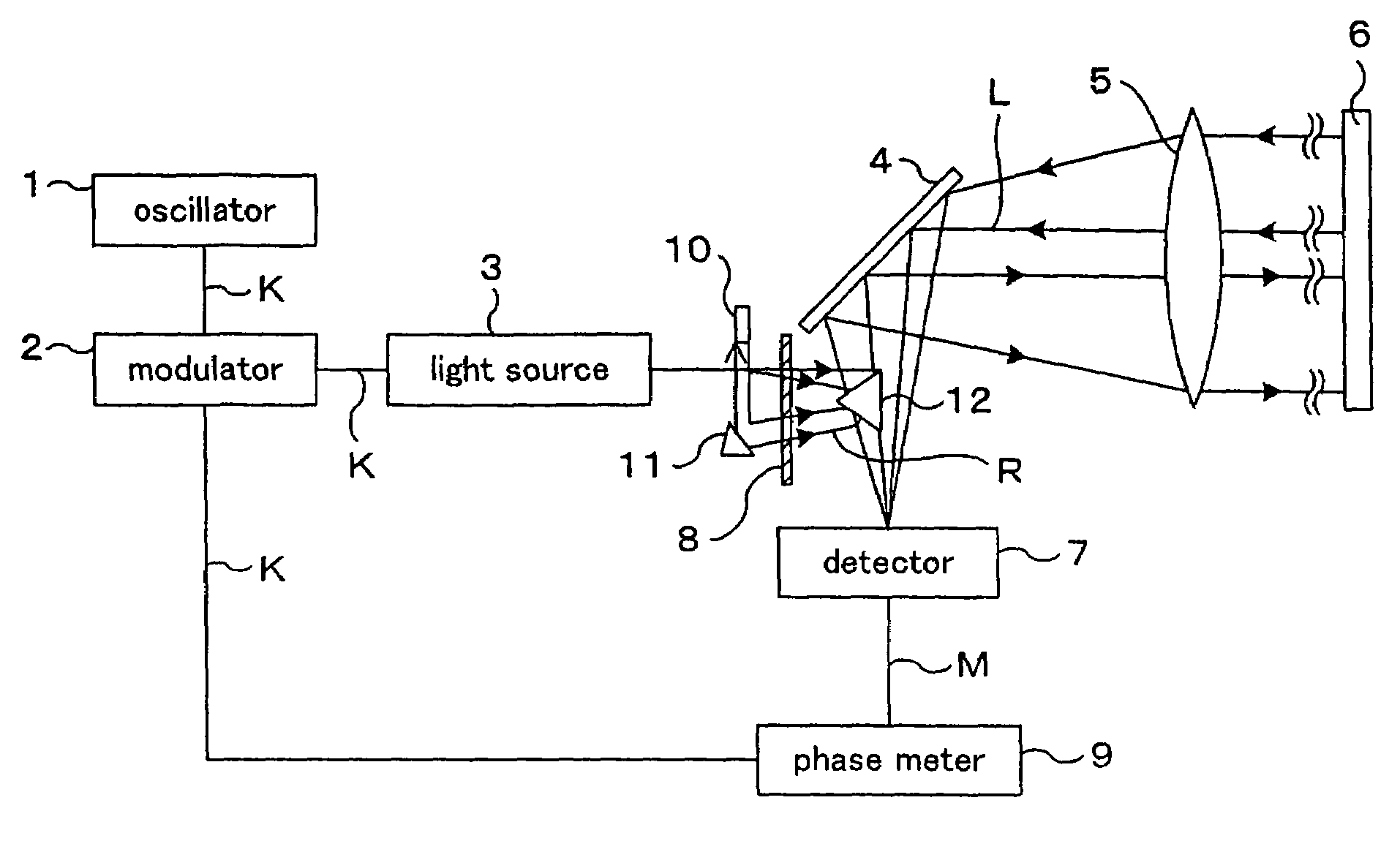
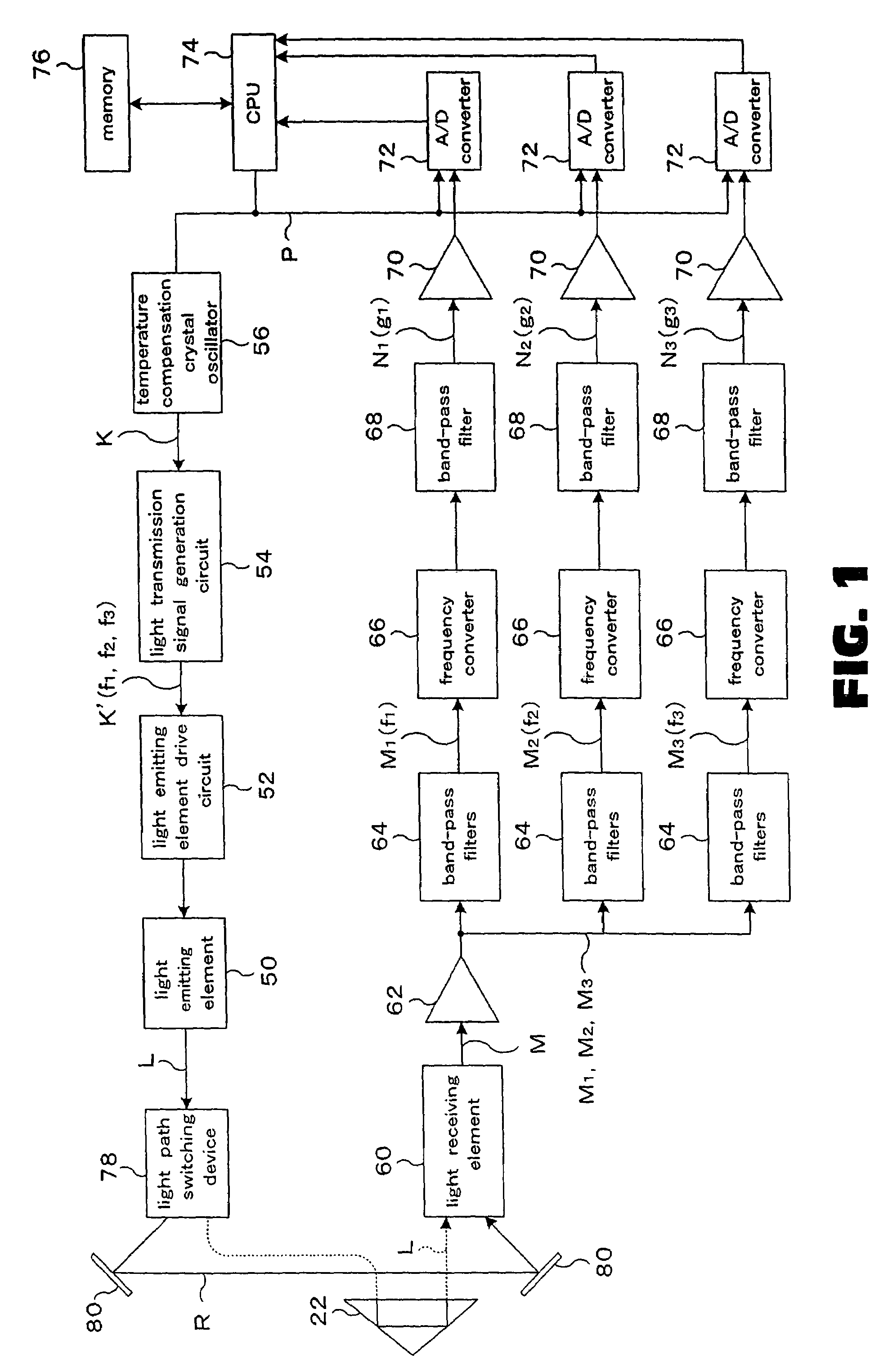
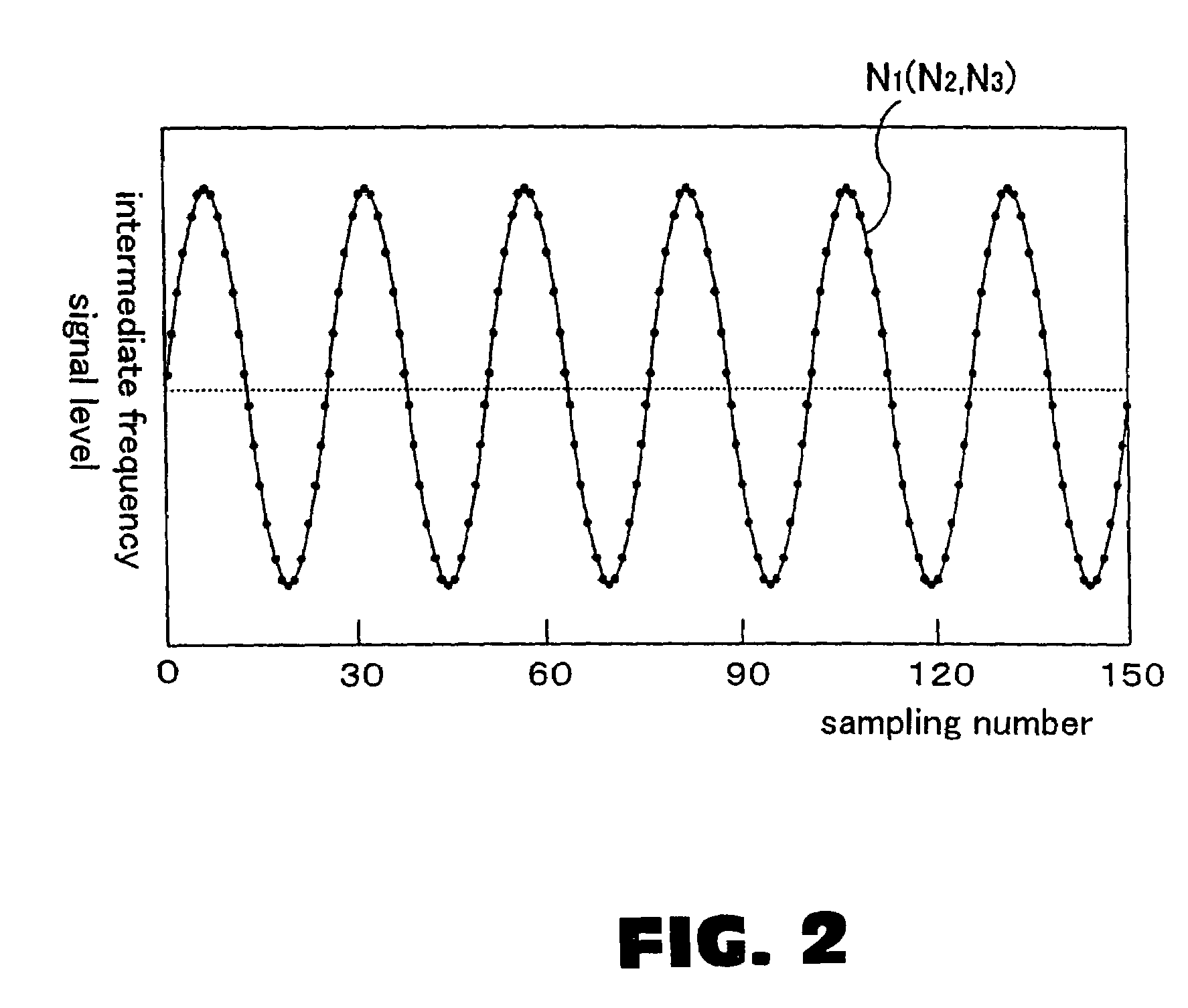
[0031]Referring now to the drawings, an example of the electric optical distance wavelength meter according to the present invention will be described below. FIG. 1 is a block diagram of the electric optical distance wavelength meter. FIG. 2 is a diagram showing the state of sampling an intermediate frequency signal in the electric optical distance wavelength meter. FIG. 3 is a flow chart showing the procedure of a light path switching processing for switching the light path of measurement light and reference light using a light path switching device in the electric optical distance wavelength meter. FIG. 4 is a view showing a principle detecting the time when the switching is completed when the measurement light and the reference light are switched by using the light path switching device.

[0032]This electric optical distance wavelength meter is provided with a light emitting element 50 (light source) such as a laser diode emitting measurement light L. The light emitting element 50 ...


PUM


Abstract

It is an object of the present invention to provide an electric optical distance wavelength meter detecting the time when the switching is completed and shortening the time required for distance measurement by immediately starting the distance measurement when measurement light and reference light are switched by a light path switching device. An electric optical distance wavelength meter includes a light emitting element for emitting measurement light toward a target placed on a measurement point; a light receiving element for receiving the measurement light coming back after reflecting on the target; a CPU for calculating the distance to the target or the object based on light receiving signals from the light receiving element; and a light path switching device for switching the measurement light so that the measurement light passes through an internal light path from the light emitting element to the light receiving element.

Description

[0001]The present invention relates to an electric optical distance wavelength meter emitting measurement light toward a target, receiving the reflected light from the target and measuring the distance to the target.BACKGROUND OF THE INVENTION[0002]An electric optical distance wavelength meter of a phase difference system disclosed in Japanese Published Examined Patent Application No. 3236941 has been often used. FIG. 5 is a block diagram of the electric optical distance wavelength meter.[0003]In the electric optical distance wavelength meter, measurement light L emitted from a light source 3 such as a laser diode is emitted toward a target (prism or the like) 6 placed on a measurement point through a light transmission optical system such as prisms 10, 12, a mirror 4 and an object lens 5. The light source 3 is connected to a modulator 2, and the modulator 2 is connected to a reference signal oscillator 1. The measurement light L is modulated by a reference signal K generated by the...

Claims


Application Information

Patent Timeline
Patent Type & Authority Patents(United States)
IPC IPC(8): G01C3/08
CPCG01C3/08G01S7/497G01S17/36
Inventor NAKAMURA, YUTAKAKIKAWA, HAYAMI
Owner SOKKOIA COMPANY LIMITED
Why Eureka
Try Eureka