Plasma display panel drive method

a plasma display panel and drive method technology, applied in the direction of instruments, static indicating devices, address electrodes, etc., can solve the problems of increasing discharge delay, difficult discharge, and rapid reduction of the priming caused by discharg

Inactive Publication Date: 2008-03-11
PANASONIC CORP
View PDF12 Cites 9 Cited by
  • Summary
  • Abstract
  • Description
  • Claims
  • Application Information

AI Technical Summary

Problems solved by technology

However, there are many factors in increasing discharge delay in the writing discharge: restraints of the circuitry inhibit the use of high voltage for write pulses; and phosphor layers formed on the data electrodes make discharge difficult.
However, the priming caused by discharge rapidly decreases as time elapses.
This causes the following problems in the method of driving a panel described above.
In writing discharge occurring a long time after the initializing discharge, priming generated in the initializing discharge is insufficient.
This insufficient priming causes a large discharge delay and an unstable writing operation, thus degrading the image display quality.
Additionally, when a long writing period is set for a stable writing operation, the time taken for the writing period is too long.

Method used


Image

  • Plasma display panel drive method
  • Plasma display panel drive method
  • Plasma display panel drive method

Examples


Embodiment Construction

[0025]A method of driving a plasma display panel in accordance with an exemplary embodiment of the present invention is described hereinafter with reference to the accompanying drawings.

Exemplary Embodiment

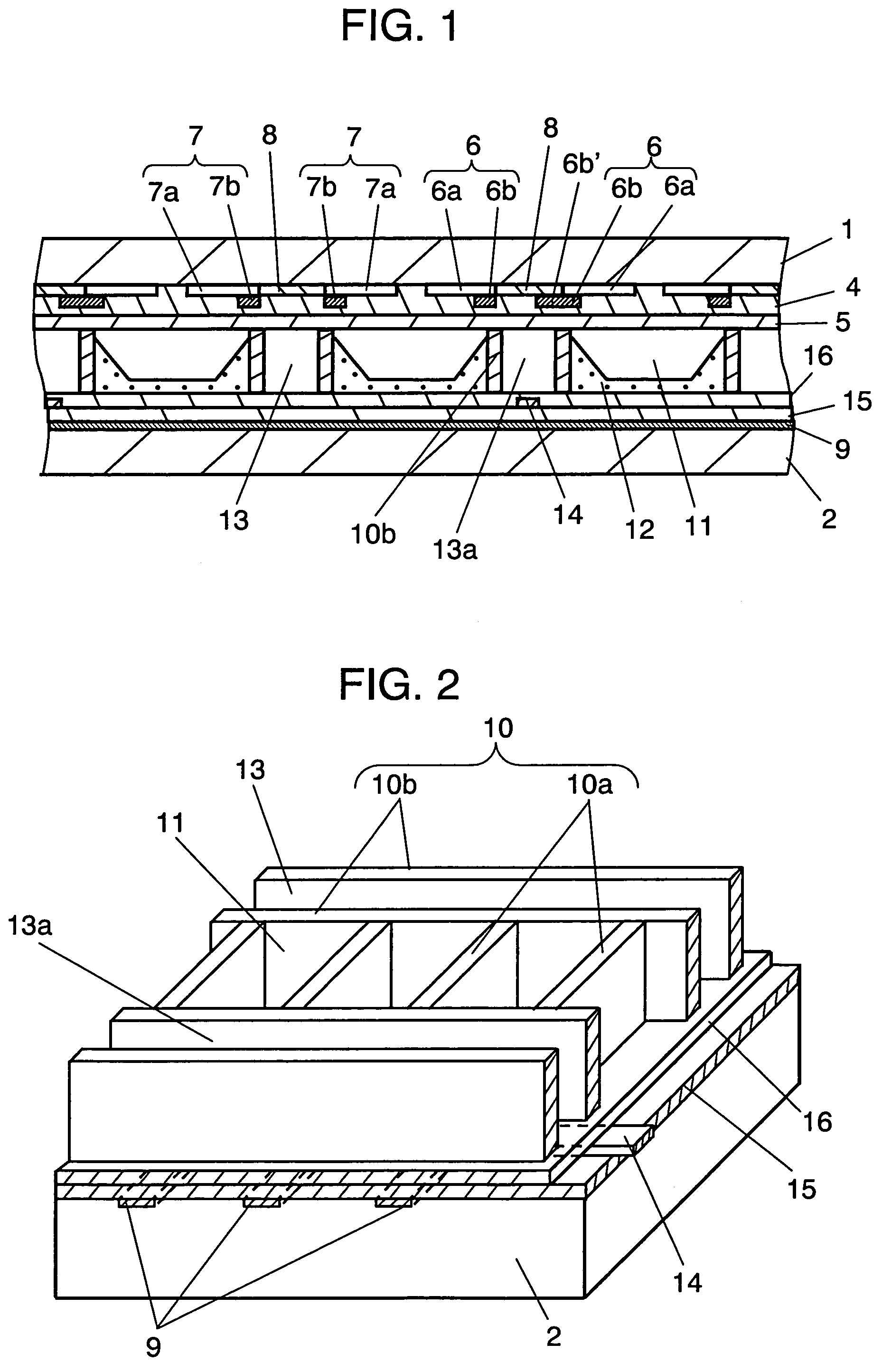
[0026]FIG. 1 is a sectional view showing an example of a panel used for the exemplary embodiment of the present invention. FIG. 2 is a schematic perspective view showing the structure of the rear substrate side of the panel.

[0027]As shown in FIG. 1, front substrate 1 and rear substrate 2 both made of glass are arranged to face each other so as to sandwich a discharge space therebetween. A mixed gas of neon and xenon for radiating ultraviolet light by discharge is filled in the discharge space.

[0028]On front substrate 1, a plurality of pairs of a scan electrode 6 and a sustain electrode 7 are formed in parallel with each other. Scan electrodes 6 and sustain electrodes 7 are alternately arranged in pairs as follows: sustain electrode 7—scan electrode 6—scan electrode 6—sustain elect...


PUM


Abstract

The initializing period of at least one of a plurality of sub-fields constituting one field is a selective initializing period for selectively initializing discharge cells in which a sustain discharge has occurred in the sustaining period of the preceding sub-field. In the sustaining period of the sub-field prior to the sub-field including the selective initializing period, voltage Vr is applied to a priming electrode (PRi) for causing a discharge between the priming electrode (PRi) and corresponding scan electrode (SCi) using the priming electrode (PRi) as a cathode.

Description

BACKGROUND OF THE INVENTION[0001]1. Field of the Invention[0002]The present invention relates to a method of driving a plasma display panel.[0003]2. Description of the Related Art[0004]A plasma display panel (hereinafter abbreviated as a PDP or a panel) is a display device having excellent visibility and featuring a large screen, thinness and a light weight. The systems of discharging a PDP include an alternating-current (AC) type and direct-current (DC) type. The electrode structures thereof include a three-electrode surface-discharge type and an opposite-discharge type. However, the current mainstream is an AC type three-electrode PDP, which is an AC surface-discharge type, because this type of PDP is suitable for higher definition and is easy to manufacture.[0005]Generally, an AC type three-electrode PDP has a large number of discharge cells formed between a front panel and rear panel facing each other. In the front panel, a plurality of display electrodes, each comprising a pair...

Claims


Application Information

Patent Timeline
Patent Type & Authority Patents(United States)
IPC IPC(8): G09G3/28G09G3/20G09G3/292G09G3/288G09G3/291G09G3/296G09G3/298H01J11/12H01J11/14H01J11/22H01J11/24H01J11/26H01J11/28H01J11/34H01J11/36
CPCG09G3/2022G09G3/2925G09G3/2927G09G3/2948G09G3/2986G09G3/293G09G3/294G09G2320/0238G09G3/292H01J11/22
Inventor TACHIBANA, HIROYUKIKOSUGI, NAOKIWAKABAYASHI, TOSHIKAZUMUTO, YASUAKI
Owner PANASONIC CORP
Why Eureka
Try Eureka