Control member with a balance wheel and a planar spiral for a watch or clock movement

a control member and watch movement technology, applied in torsion springs, instruments, horology, etc., can solve the problems of significant disturbance of the operation of the hairspring, and achieve the effect of significantly improving the isochronism of the balance and hairspring assembly

Active Publication Date: 2008-03-18
PATEK PHILIPPE SA
View PDF5 Cites 25 Cited by
  • Summary
  • Abstract
  • Description
  • Claims
  • Application Information

AI Technical Summary

Benefits of technology

[0011]The present invention seeks to improve the isochronism of a balance and hairspring assembly by stiffening a portion of the outer turn of the hairspring, and for this purpose the invention provides a regulating device as defined in the appended claims as well as a timepiece, such as a watch, incorporating the above-mentioned regulating device.
[0012]The present invention is based on the observation that, contrary to the conclusions reached by the authors of the above-mentioned article “Spiraux plats concentriques sans courbes”, it is possible to improve significantly the isochronism of a balance and hairspring assembly by stiffening a determined portion of the outer turn of the hairspring, provided that the spacing between the terminal portion of the outer turn and the last-but-one turn of the hairspring is sufficiently large to ensure that said last-but-one turn remains radially free during expansions of the hairspring up to amplitudes corresponding substantially to the maximum angle of rotation of the balance in the movement.

Problems solved by technology

According to the present inventors, the reason why the solution using angle strip in the outer turn as described in the above-mentioned article provided no improvement in terms of isochronism, stems from the fact that during large-amplitude expansions of the hairspring the last-but-one turn came into abutment against the outer turn or against a stud or an index pin associated with said outer turn, thereby significantly disturbing the operation of the hairspring.

Method used


Image

  • Control member with a balance wheel and a planar spiral for a watch or clock movement
  • Control member with a balance wheel and a planar spiral for a watch or clock movement
  • Control member with a balance wheel and a planar spiral for a watch or clock movement

Examples


Embodiment Construction

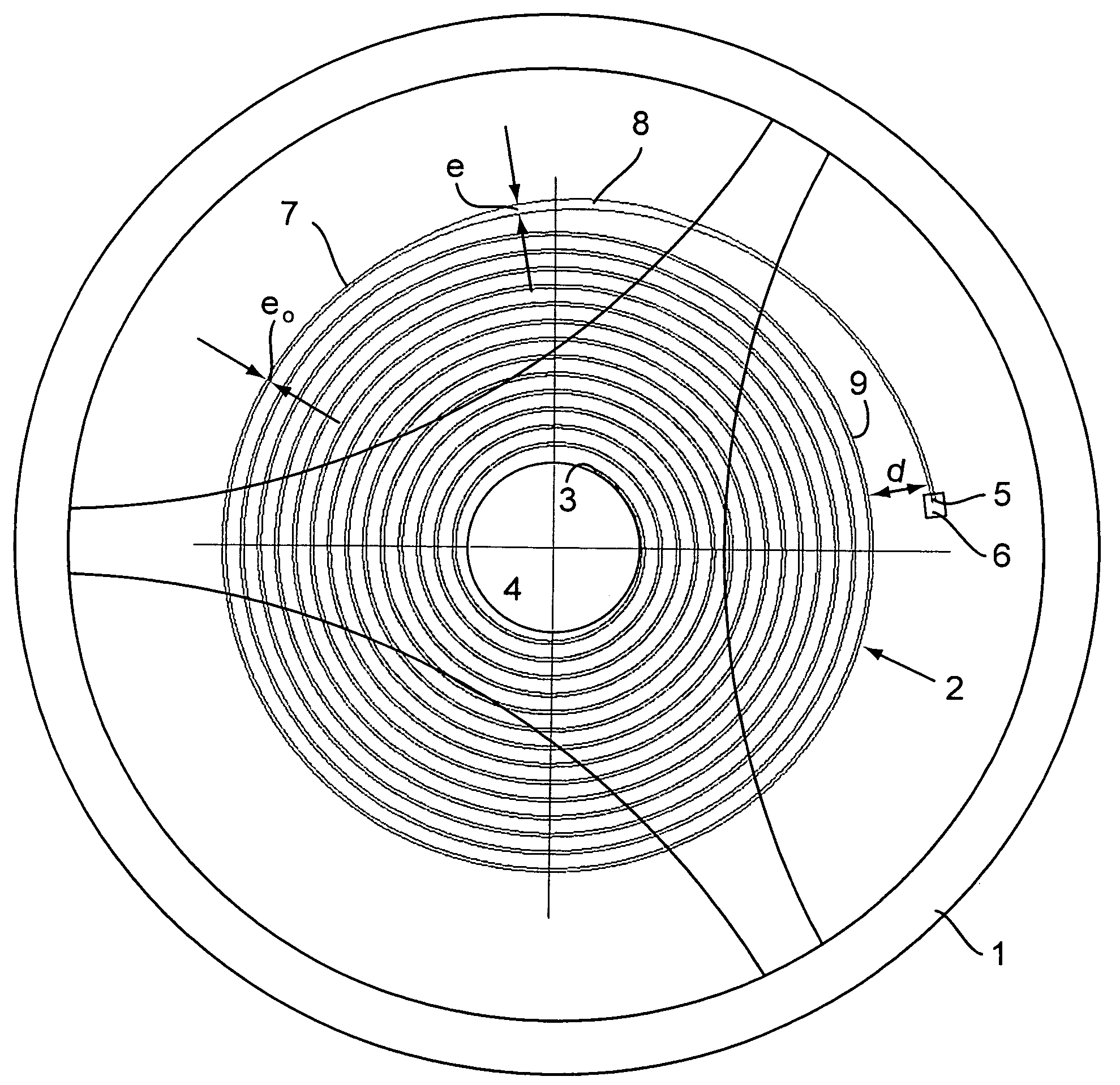
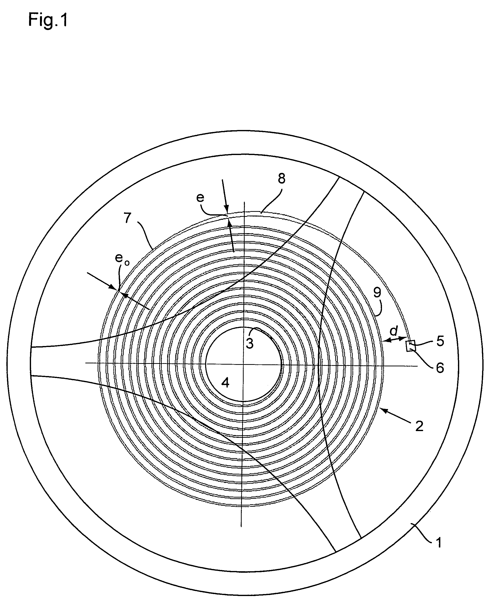
[0026]With reference to FIG. 1, a regulating device for a time piece movement according to the invention comprises a balance 1 and a flat hairspring 2 in the form of an Archimedes' spiral. The inner end 3 of the hairspring 2 is fixed to a collet 4 driven onto the shaft of the balance 1 and is therefore continuously subjected to the rotary torque from the balance 1. In known manner, the rotary shaft of the balance and hairspring assembly turns in bearings (not shown). The outer end 5 of the hairspring 2 is fixed to a stationary part of the movement, typically the balance-cock, via a fixing member 6 called “stud”.

[0027]According to the invention, the hairspring 2 has in its outer turn 7 a stiffened portion 8 that is arranged to cause the deformations of the turns to be substantially concentric during expansions and compressions of the hairspring 2. This stiffened portion 8 is constituted by a portion of the strip forming the hairspring having a greater thickness e in the plane of the ...


PUM


Abstract

A regulating device including a balance (1) and a plane hairspring (2) for a time piece movement, the plane hairspring (2) including a stiffened portion (8) in its outer turn (7) that is arranged to cause the deformations of the turns to be substantially concentric. The spacing (d) between a terminal portion of the outer turn (7) and the last-but-one turn (9) of the hairspring (2) is large enough for said last-but-one turn (9) to remain free radially during expansions of the hairspring (2) up to amplitudes corresponding substantially to the maximum angle of rotation of the balance (1) in the movement.

Description

BACKGROUND[0001]A. Field[0002]The present invention relates to a regulating device having a balance and a plane hairspring for a time piece movement.[0003]B. Related Art[0004]It is known that the turns of a plane hairspring deform eccentrically when the hairspring is in operation. This eccentric deformation of the turns, which is explained by the fact that the center of gravity of the hairspring does not correspond to the center of rotation of the balance and hairspring assembly, disturbs the setting of the balance and hairspring assembly and makes it anisochronous.[0005]The center of gravity of the hairspring could be returned arbitrarily to the center of rotation of the balance by being shifted, however that would not solve the problem since during the working of the hairspring the center of gravity would move and would therefore no longer coincide with the initial center of gravity.[0006]Two different solutions have been proposed for causing the center of gravity and the center o...

Claims


Application Information

Patent Timeline
Patent Type & Authority Patents(United States)
IPC IPC(8): G04B17/04F16F1/10F16F1/14G04B17/06
CPCF16F1/10F16F1/14G04B17/066
Inventor MUSY, JEAN-PIERREMAIER, FREDERICBELOT, MICHEL
Owner PATEK PHILIPPE SA
Why Eureka
Try Eureka