Device for fabricating a composite material part

a composite material and device technology, applied in the field of devices for fabricating composite materials, can solve the problems of irregular structure of the casing, uneven resin mass between the layers, and compact defects, and achieve the effect of disturbing the assembly operation

Active Publication Date: 2017-03-14
SN DETUDE & DE CONSTR DE MOTEURS DAVIATION S N E C M A
View PDF9 Cites 0 Cited by
  • Summary
  • Abstract
  • Description
  • Claims
  • Application Information

AI Technical Summary

Benefits of technology

[0014]By means of the link(s), the positioning of the chock in the reentrant angle defined between the two support surfaces of the first die, and thus the pressing of the fiber structure into this angle, takes place automatically as the dies approach each other. In comparison with the previously known manual positioning method, such automatic positioning of the chock is faster, more reliable (less risk of human error), and presents the advantage of being compatible with mass production rates of throughput.
[0016]In certain embodiments, a gasket is arranged between the third face and the second die around the link. This gasket serves to avoid resin passing between the chock and the second die, and in particular to avoid resin clogging up and thus jamming the link and disturbing the operation of the assembly.
[0017]In certain embodiments, the chock is connected to the second die by at least one pair of mutually parallel links. This makes it possible to guide the chock and to distribute the forces among the links, and thus to guarantee that the connection is reliable and long-lasting over production cycles.

Problems solved by technology

During the impregnation step, it has been found that the layers of the fiber strip tend to become tensioned and to separate from the reentrant angles defined between the cheekplates and the central wall of the mandrel, thereby leading to compacting defects and to resin masses between the layers, and consequently to irregularity in the structure of the casing in these angles.
Unfortunately, chocks are conventionally put into place manually: the chocks are put into position manually by touch, while blind, and they are subsequently fastened by being screwed to another portion of the mold.
This step of putting the chocks into place is thus an operation that is slow and difficult and not compatible with mass production throughput rates, and it can also lead to chocks being poorly positioned.

Method used


Image

  • Device for fabricating a composite material part
  • Device for fabricating a composite material part
  • Device for fabricating a composite material part

Examples


Embodiment Construction

)

[0034]An embodiment is described in detail below with reference to the accompanying drawings. This embodiment shows the characteristics and advantages of the invention. Nevertheless, it should be understood that the invention is not limited to this embodiment. In particular, although the invention is described below in the context of its application to fabricating an aeroengine fan casing, the invention is not limited to that application.

[0035]An implementation of a method of fabricating a fan casing is described in document EP 1 961 923, to which reference may be made.

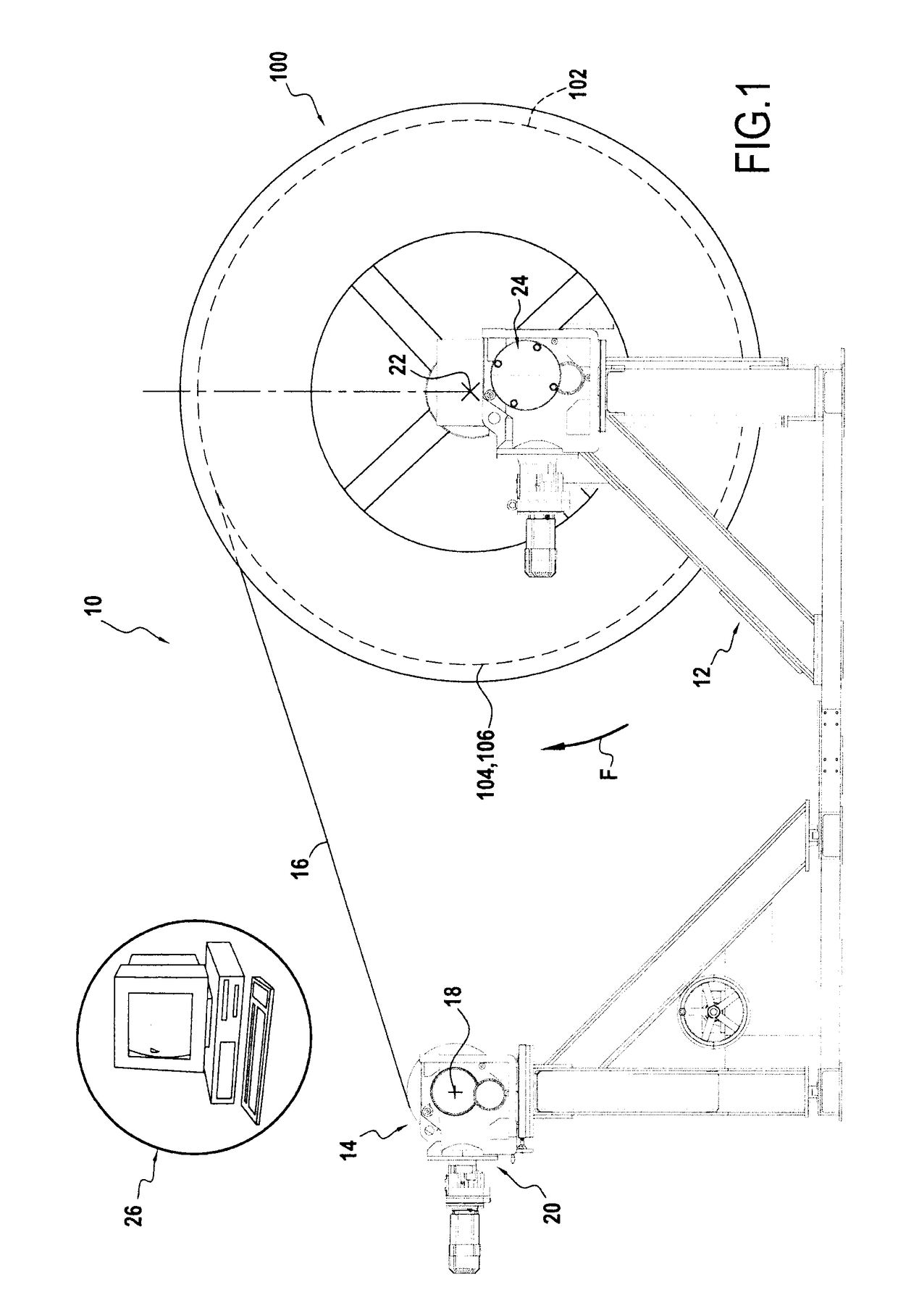
[0036]Briefly, the fabrication method described in EP 1 961 923 consists in making a fiber strip or sheet by three-dimensional weaving with warp take-up on a drum, referred to below as the “take-up mandrel”. The fiber sheet as made in this way is subsequently transferred onto the mandrel of a resin injection mold, referred to below as the “impregnation mandrel”, with the outside shape of this mandrel matching the ins...


PUM

PropertyMeasurementUnit
angleaaaaaaaaaa
reentrant angleaaaaaaaaaa
circumferenceaaaaaaaaaa

Abstract

A device for fabricating a composite material part by injecting resin into a fiber structure. The device includes: a first die presenting two adjacent support surfaces defining a reentrant angle between them; at least one chock with a wedge-shaped portion configured to press the fiber structure into the angle; and a second die movable relative to the first die, the first and second dies being configured to clamp on the fiber structure and the chock. The chock is connected to the second die by at least one link, the link being hinged relative to the second die and relative to the chock to guide the wedge-shaped portion towards the angle to press the fiber structure into the angle when the second die approaches the first die.

Description

FIELD OF THE INVENTION[0001]The present description relates to a device for fabricating a composite material part.[0002]Such a device may be used for fabricating a composite material part and in particular for fabricating an aeroengine fan casing.STATE OF THE PRIOR ART[0003]In an aeroengine, the fan casing generally performs several functions. It defines an air inlet passage into the engine, it supports an abradable material in register with the tips of the fan blades, it supports an optional structure for acoustic treatment at the inlet to the engine, and it incorporates or supports a retention shield. The shield constitutes a trap for retaining debris, such as ingested objects or fragments of damaged blades projected outwards by centrifuging, in order to prevent such debris from passing through the casing and reaching other portions of the airplane.[0004]It is known to make fan casings out of composite material. By way of example, document EP 1 961 923 describes a method of fabric...

Claims


Application Information

Patent Timeline
Patent Type & Authority Patents(United States)
IPC IPC(8): B29C33/48B29C70/46B29C33/20B29C33/42B29C70/34B29C70/48B29C45/00B29K63/00B29K79/00B29K307/04B29K309/02B29K309/08B29L9/00B29L31/00B29L31/30
CPCB29C33/48B29C33/20B29C33/42B29C33/485B29C45/0005B29C70/34B29C70/46B29C70/462B29C70/48B29K2063/00B29K2079/08B29K2277/10B29K2307/04B29K2309/02B29K2309/08B29L2009/00B29L2031/3076B29L2031/7504
Inventor PLANTE, ROMAINCANAVESE, CLAUDEPINGON, DENISDURAND, JEAN-FRANCOIS
Owner SN DETUDE & DE CONSTR DE MOTEURS DAVIATION S N E C M A
Why Eureka
Try Eureka