
Timepiece movement

a timepiece and movement technology, applied in the field of horology, can solve the problems of limiting the freedom of the horologist and the solution would be very limited in terms of possibilities, and achieve the effect of improving the isochronism of the movemen

Inactive Publication Date: 2020-08-13
FORSEY STEPHEN +3
View PDF9 Cites 0 Cited by
  • Summary
  • Abstract
  • Description
  • Claims
  • Application Information

AI Technical Summary

Benefits of technology

The patent text describes a way to optimize the movement of a display by averaging the operation of four regulating systems and allowing for the flexible placement of the display based on the needs of the system. This approach also includes the use of a constant force system to improve the isochronism of the movement. The technical effects of this innovation include improved accuracy and flexibility in the display movement.

Problems solved by technology

However, the motion-work is arranged conventionally relative to the going train, which imposes limitations on the freedom of the horologist to optimize the transmission of torque and to choose the rotation speeds of the wheels, tourbillons, etc.
However, this solution would be very limited in terms of the possibilities for the spatial arrangement of the seconds wheels in the movement.

Method used


Image

  • Timepiece movement
  • Timepiece movement

Examples


Embodiment Construction

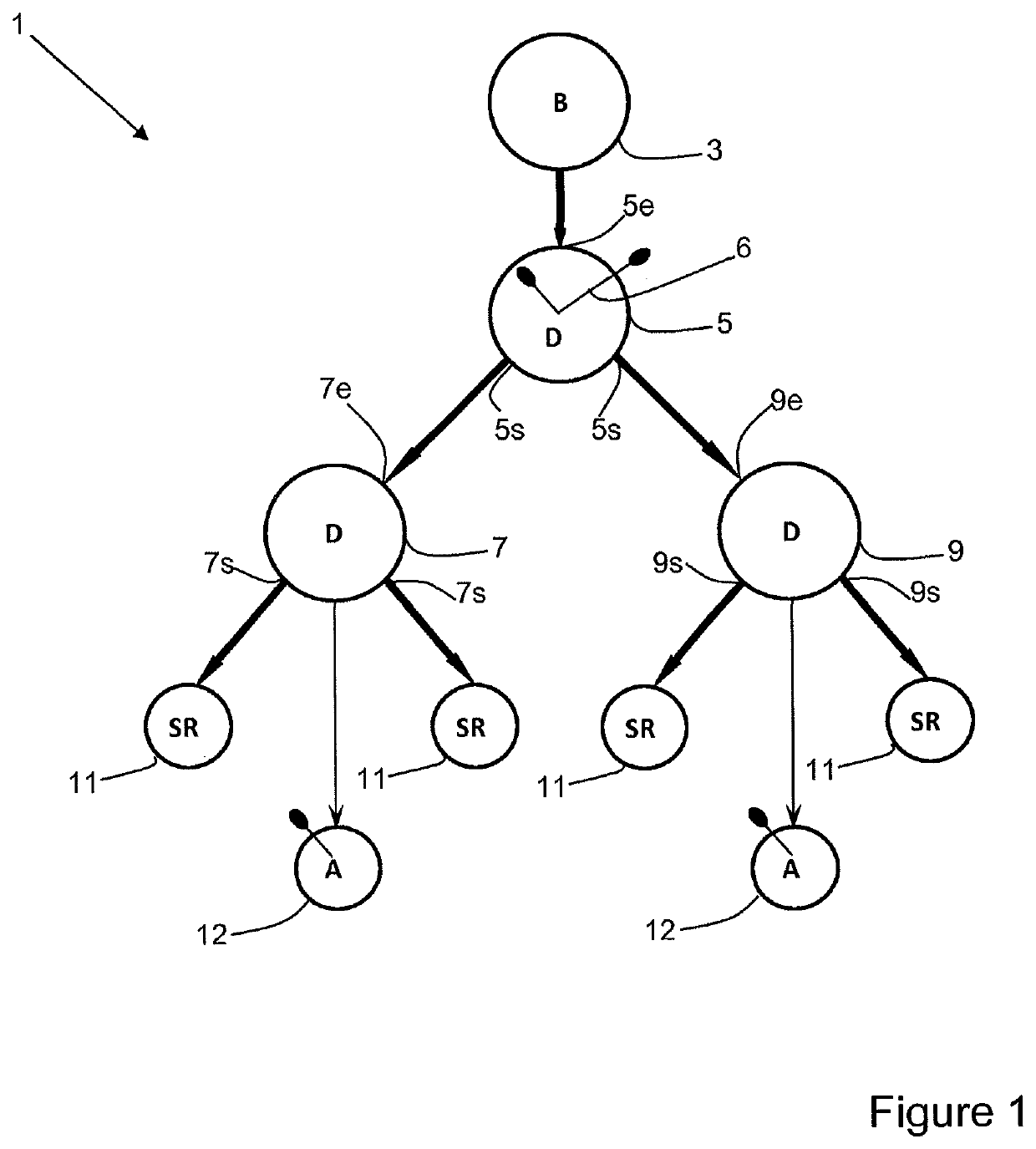
[0025]FIG. 1 schematically shows one embodiment of a timepiece movement 1 according to the invention.

[0026]The movement 1 comprises a motor organ 3, which may for example be one or several motor springs stored in one or several barrels in series and / or in parallel.

[0027]The motor organ 3 is kinematically linked with an input 5e of a first differential gear 5 formed by appropriate wheels. This differential gear 5 can be of any type, for example a spherical type, a flat type or any other configuration. The differential gear 5 as defined in the present invention comprises an input 5e and two outputs 5s. The mechanical link between the input 5e and the outputs 5s can be effected in any typical manner, for example via one or several satellite pinions, one or several resilient elements or any mechanism allowing a function equivalent to these latter. It may also comprise at least one constant force differential as described in document EP 2,548,084, herewith incorporated by reference in it...


PUM


Abstract

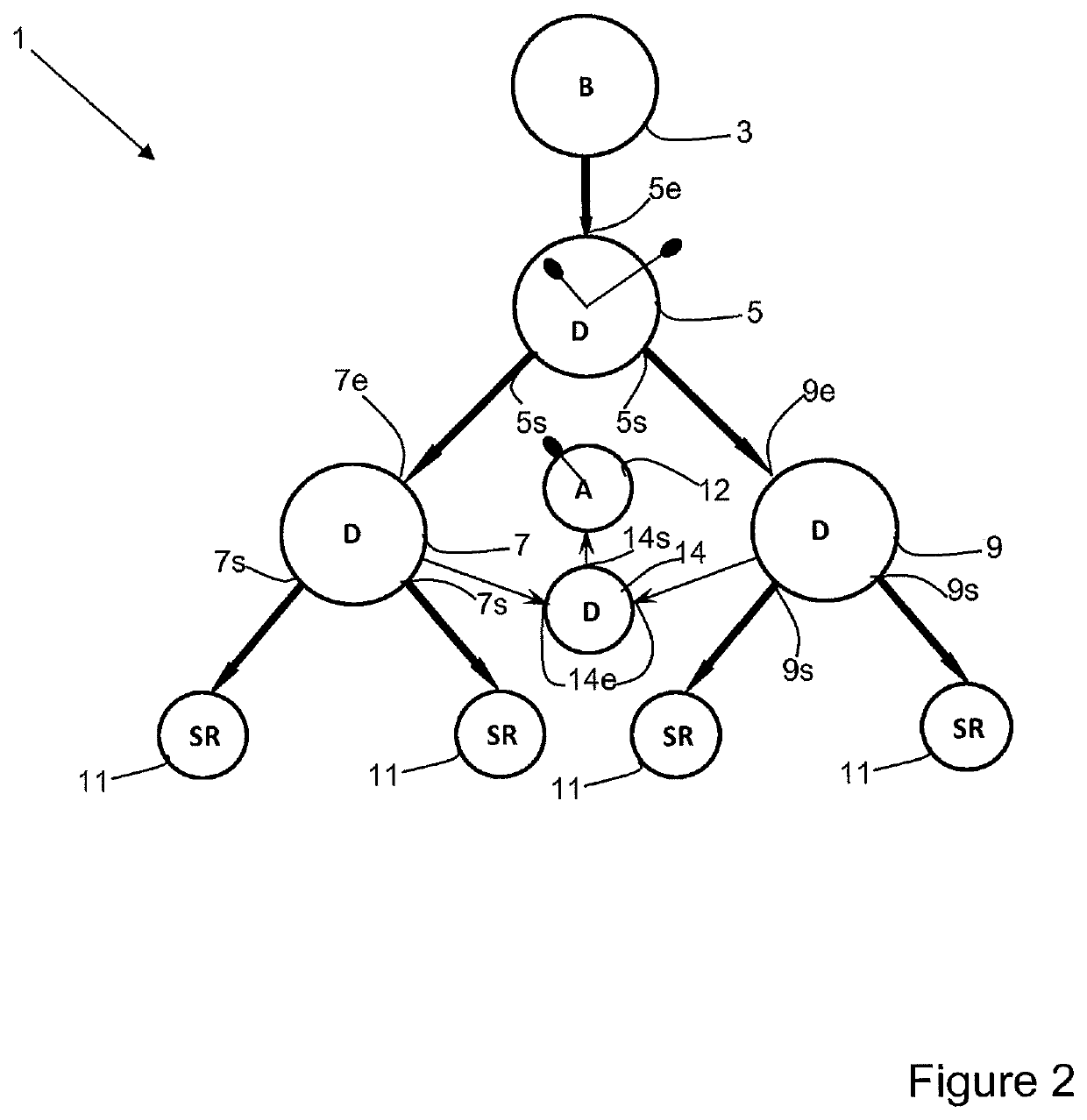
Horology movement comprising:—at least one drive member; four regulating systems, each being kinematically connected with the said drive member via a drive kinematic network designed to transmit energy from the drive member to the said regulating systems; in which the said drive kinematic network comprises: a first differential gear set having an input kinematically connected to the drive member and having two outputs; a second and a third differential gear set each having an input kinematically connected to a respective output (5s) of the first differential gear set and each having two outputs, each of the latter outputs being kinematically connected to a respective regulating system; the said movement further comprising: an hours and minutes display device designed to be driven by the first differential gear set; at least one seconds display device designed to be driven by at least one of the second and third differential gear sets via a kinematic connection which branches off the said drive kinematic network, the said seconds display device comprising a seconds indicating member rotating as one with a mobile that meshes directly or indirectly with a mobile that the said drive kinematic network comprises

Description

TECHNICAL FIELD[0001]The present invention relates to the field of horology. It more particularly relates to a timepiece movement comprising a plurality of regulating systems.BACKGROUND OF THE INVENTION[0002]Document EP 1,706,796 describes a timepiece movement comprising two tourbillons connected to a shared motor organ via a differential gear. This differential gear allows the tourbillon cages to rotate independently of one another, and serves to average their running. The wheels of the going train therefore rotate at angular speeds in function of the average of the running of the two tourbillons, which serves to improve the precision of the running of the movement.[0003]However, the motion-work is arranged conventionally relative to the going train, which imposes limitations on the freedom of the horologist to optimize the transmission of torque and to choose the rotation speeds of the wheels, tourbillons, etc.[0004]Document WO 2013 / 104982 discloses a timepiece comprising four reg...

Claims


Application Information

Patent Timeline
Patent Type & Authority Applications(United States)
IPC IPC(8): G04B19/02
CPCG04B19/02G04B17/00G04B19/26
Inventor FORSEY, STEPHENTRIFONI, FRANCOISTRIFRONI, FRANCOISBERNARD, DAVID
Owner FORSEY STEPHEN
Learn More