Electrical connecting device

a technology of electrical connection and connecting device, which is applied in the direction of contact members penetrating/cutting insulation/cable strands, electrical apparatus, fastening/insulating connecting parts, etc., can solve problems such as insulation problems, and achieve the effect of increasing the dimensions of the electrical connection devi

Inactive Publication Date: 2008-03-18
PHOENIX CONTACT GMBH & CO KG
View PDF13 Cites 7 Cited by
  • Summary
  • Abstract
  • Description
  • Claims
  • Application Information

AI Technical Summary

Benefits of technology

[0009]A primary object of the electrical connecting device of the present invention is achieved by the conductor receiver in the actuating elements being made such that at least two insulated conductors can be inserted into the conductor receiver. This makes it possible especially easily without significantly increasing the dimensions of the electrical connecting device to connect twice the number of insulated conductors to the connecting device.
[0010]Basically, there are various possibilities for how the conductor receiver is specifically made in the actuating elements. Preferably, the conductor receiver is made such that two insulated conductors can be inserted in succession into the conductor receiver in the lengthwise direction of the connecting device. In this way, on the one hand, widening of the electrical connecting device is prevented, and on the other hand, the pivoting of the actuating element out of the first position in which the incoming conductors can be inserted (insertion position) into the second position in which contact with the conductors is made by the insulation piercing element (contact position) is only slightly more complex, since the two insulated conductors are inserted when pivoted in succession between the two cutting edges of the insulation piercing element.
[0011]To insert at least two insulated conductors at a time into the actuating elements, the conductor receiver, according to a preferred version of the invention, has an oblong cross section. However, basically, it is also possible to make two separate, successively arranged conductor receivers in each actuating element. However, by forming only one conductor receiver with an oblong cross section, the dimensions of the actuating elements, and thus, also the electrical connecting device can be further reduced.

Problems solved by technology

Since a special tool is necessary for stripping the electrical conductors, and since stripping is relatively time-consuming, for many years, electrical connecting devices have also been used to which electrical conductors can be connected without prior stripping.
However, the wheel-like guide of the actuating elements in the side wall has the disadvantage that problems can arise in adherence to the required creepage distances, and thus, insulation problems can occur.

Method used


Image

  • Electrical connecting device
  • Electrical connecting device
  • Electrical connecting device

Examples


Embodiment Construction

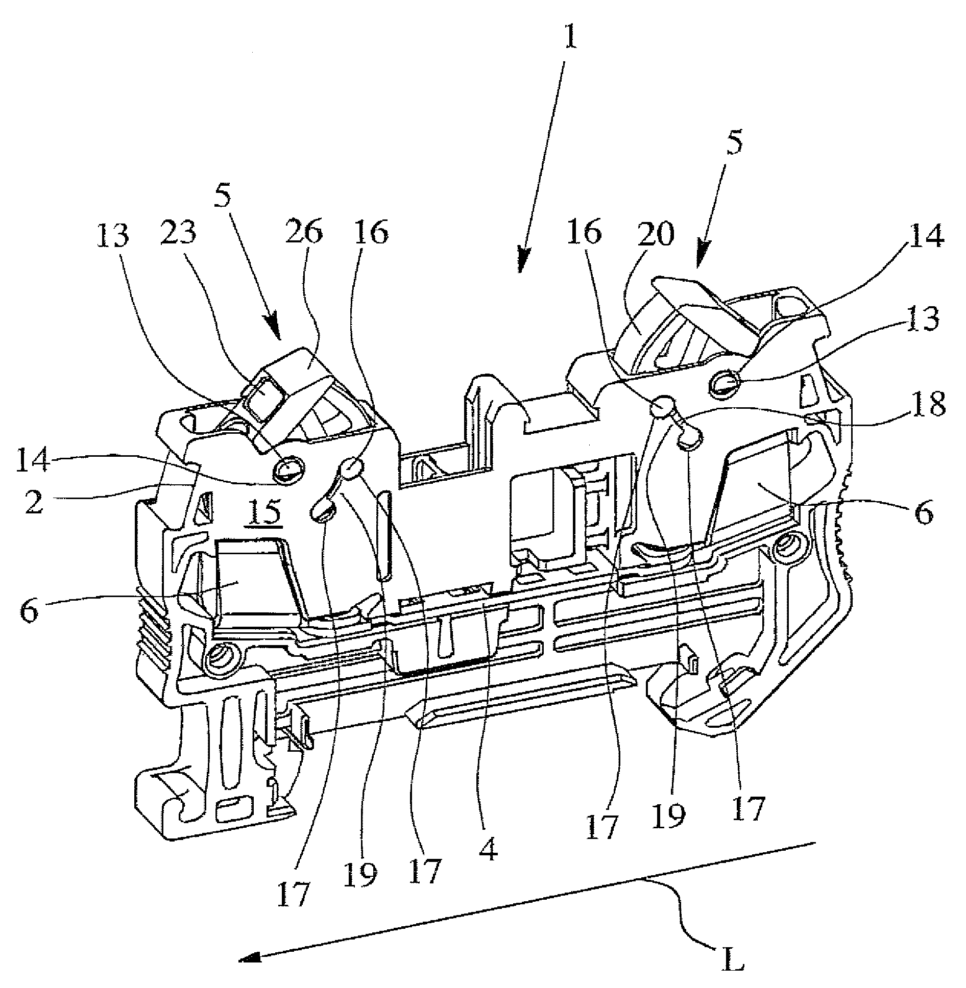
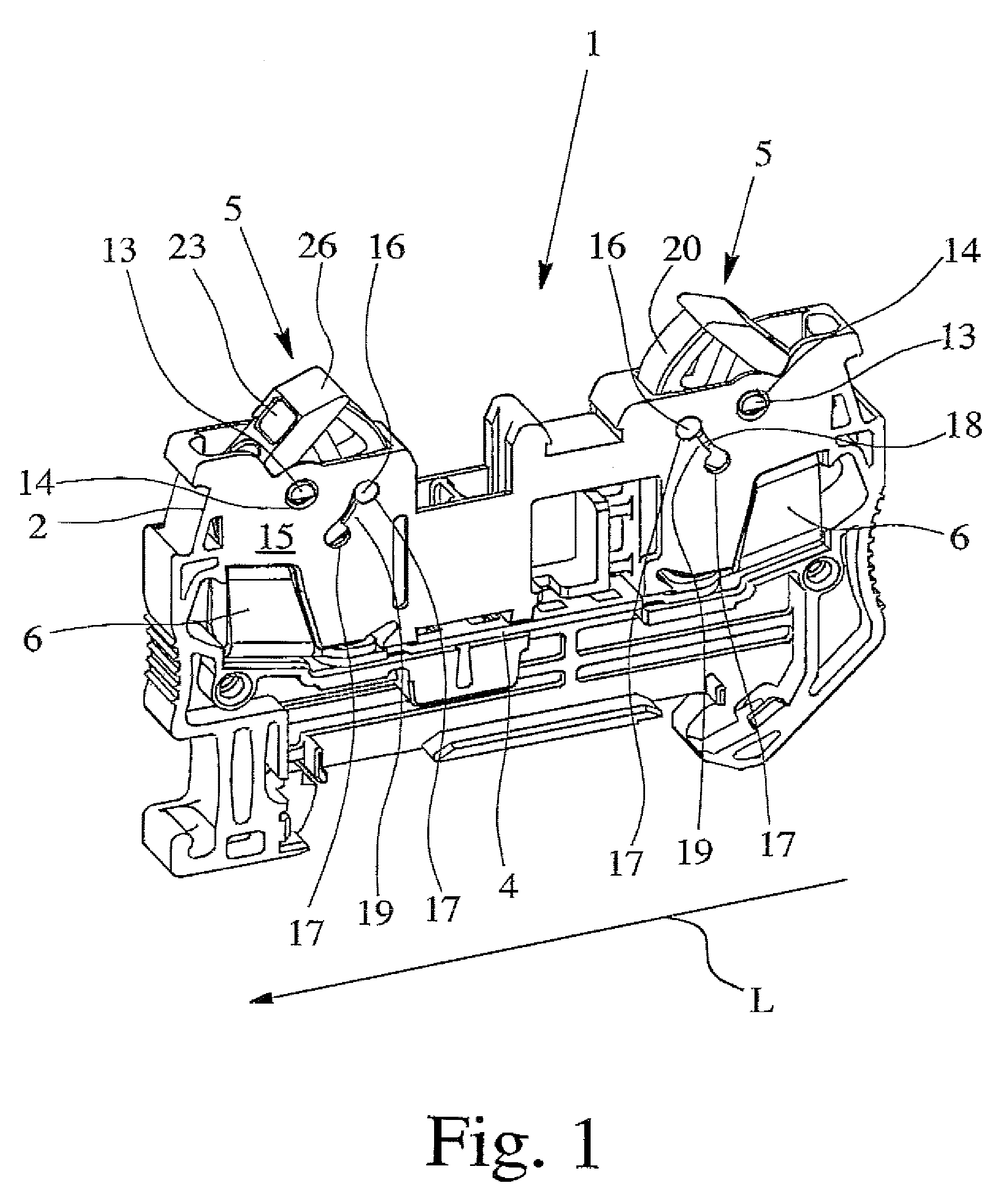
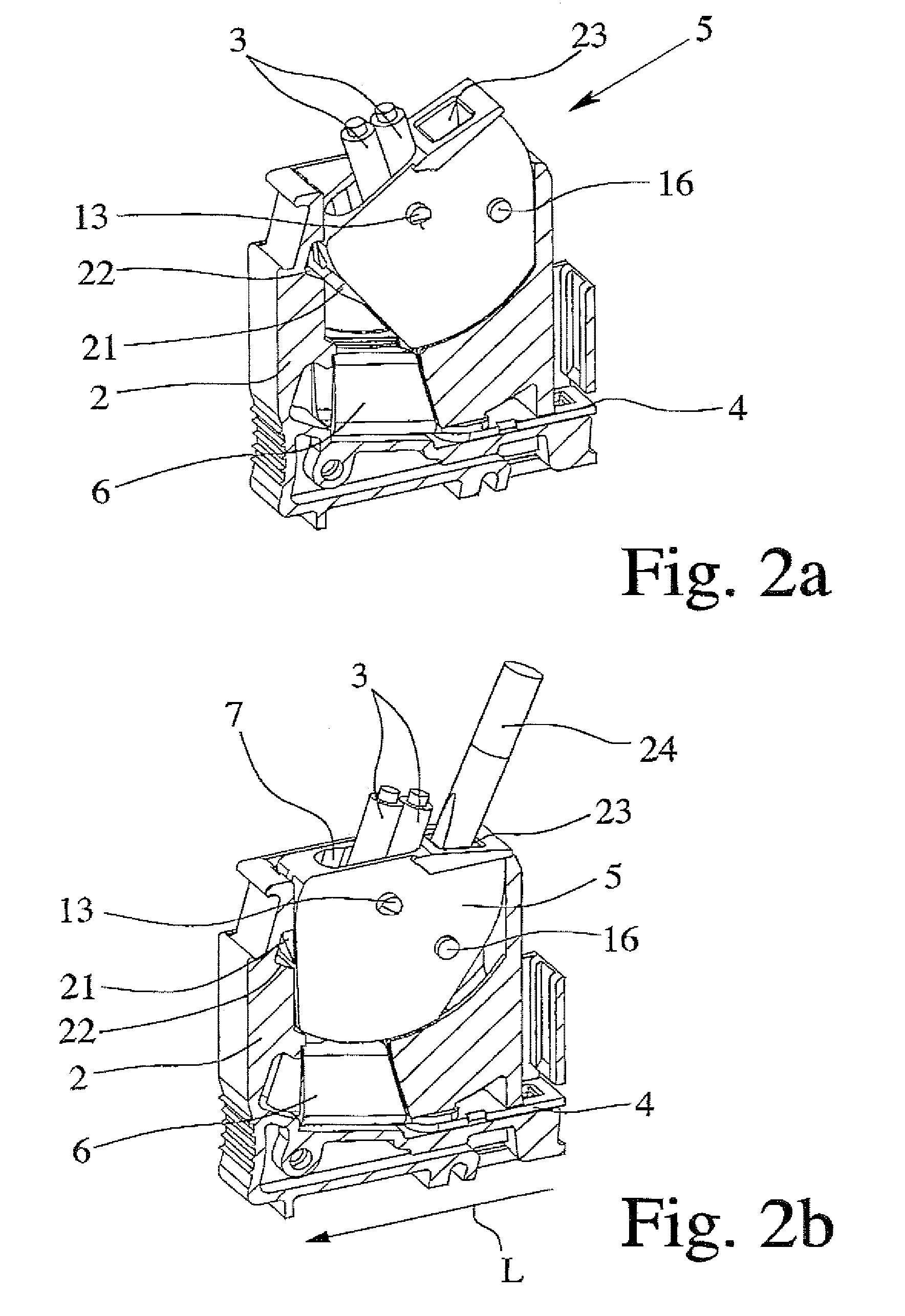
[0024]The electrical connecting device 1 which is shown in its entirety only in FIG. 1 comprises, first of all, a housing 2, with terminals for the incoming, insulated conductors 3 shown in FIGS. 2 & 3. Using the correspondingly made foot of the housing 2, the electrical connecting device 1 can be locked onto a mounting rail (not shown). A conductor bar 4 and two actuating elements 5 are located in the housing 2 of the electrical connecting device 1. Moreover, the electrical connecting device 1 has two insulation piercing elements 6 which are mechanically and electrically connected to the conductor rail 4 and which are electrically connected to one another via the conductor bar 4, so that the electrical connecting device 1 shown in FIG. 1 is a connecting terminal unit.

[0025]The actuating elements 5, of which two embodiments are shown separately in FIGS. 4 and 5, each have one conductor receiver 7 for the insulated conductors 3 to be connected. Because the actuating elements 5 are ar...


PUM


Abstract

An electrical connecting device with a housing, with terminals for insulated conductors, with at least one conductor bar, with at least two actuating elements and with at least two insulation piercing elements, the actuating elements being arranged to be able to turn relative to the insulation piercing elements and each having a conductor receiver for the conductors to be connected. The insulation piercing elements establish electrical contact of a conductor which has been inserted into the conductor receiver to the conductor bar, when the actuating element is pivoted out of a first position, in which the conductor can be inserted into the conductor receiver into a second position. By the conductor receiver being able to have at least two insulated conductors can be inserted therein, the possible applications are further enhanced, and the dimensions of the connecting device can be as small as possible.

Description

BACKGROUND OF THE INVENTION[0001]1. Field of the Invention[0002]The invention relates to an electrical connecting device with insulation piercing technology, with a housing, with terminals for insulated conductors, with at least one conductor bar, with at least two actuating elements and with at least two insulation piercing elements, the actuating elements being arranged to be able to turn relative to the insulation piercing elements in the electrical connecting device and each having a conductor receiver for the conductors to be connected, and the insulation piercing elements establishing electrical contact of a conductor inserted into the conductor receiver to the conductor bar, when an actuating element is pivoted out of a first position in which the conductor can be inserted into the conductor receiver (insertion position) into a second position (contact position).[0003]2. Description of Related Art[0004]Electrical connecting devices, especially modular connecting devices, have...

Claims


Application Information

Patent Timeline
Patent Type & Authority Patents(United States)
IPC IPC(8): H01R4/24
CPCH01R4/2433H01R9/26
Inventor WILINSKI, BERND
Owner PHOENIX CONTACT GMBH & CO KG
Why Eureka
Try Eureka