Omni-wheel, frictional propulsion device and omni-directional vehicle

a technology of frictional propulsion and omni-wheel, which is applied in the direction of friction roller based transmission, cycles, transportation and packaging, etc., can solve the problems of high complexity and high cost, significant weight, and high cost, and achieve adequate mechanical strength and stiffness, increase the dimension or weight of the core member, and reduce the effect of manufacturing cos

Active Publication Date: 2016-10-20
HONDA MOTOR CO LTD
View PDF0 Cites 7 Cited by
  • Summary
  • Abstract
  • Description
  • Claims
  • Application Information

AI Technical Summary

Benefits of technology

[0020]According to the omni-wheel of the present invention, the manufacturing cost can be reduced owing to the simple structure thereof, and an adequate mechanical strength and stiffness can be ensured without increasing the dimensions or the weight of the core member.

Problems solved by technology

The annular core members of conventional omni-wheels were known to be costly and heavy because they were made by machining or casting metallic members.
Various proposals have been made for joining the two pieces together, but have suffered from the problems of high complexity and high cost.
Furthermore, in order to ensure the necessary mechanical strength, the annular core member is required to have a significant thickness, and hence a significant weight.

Method used


Image

  • Omni-wheel, frictional propulsion device and omni-directional vehicle
  • Omni-wheel, frictional propulsion device and omni-directional vehicle
  • Omni-wheel, frictional propulsion device and omni-directional vehicle

Examples


Embodiment Construction

)

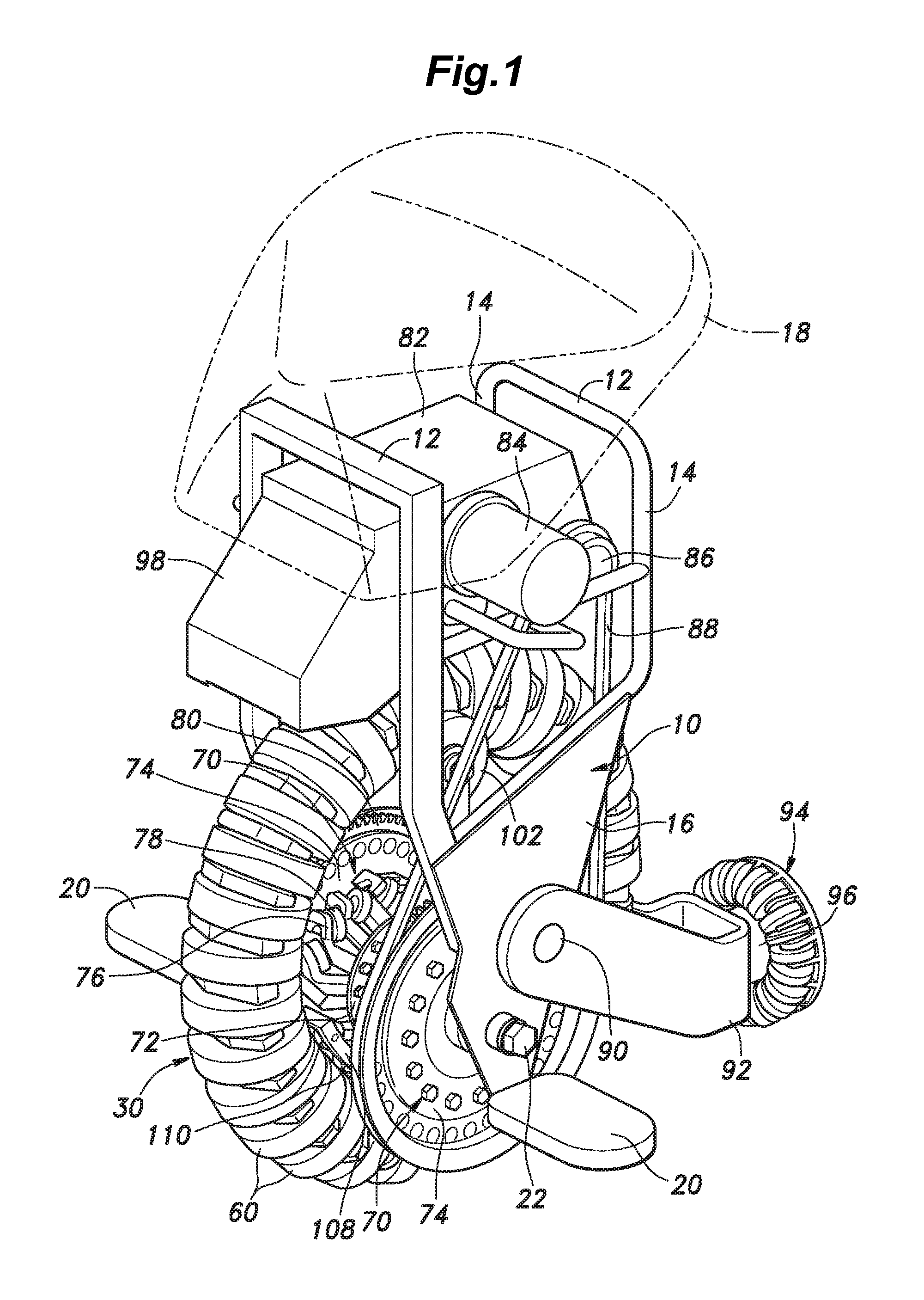
[0032]A preferred embodiment of the present invention is described in the following with reference to FIGS. 1 to 9.

[0033]As shown in FIG. 1, the inverted pendulum vehicle of the illustrated embodiment (omni-directional vehicle) comprises a vehicle body frame 10. The vehicle body frame 10 comprises a pair of upper cross members 12, and a pair of side leg members 14 each having a pair of bifurcated upper parts connected to the lateral ends of the corresponding cross members 12, respectively, and a lower part connected to a triangular lower support plate 16 extending along either side of the vehicle. The upper cross members 12 support a saddle 18 for seating the rider, and each lower support plate 16 is fitted with a foot rest 20 for supporting the corresponding foot of the rider.

[0034]A main wheel 30 and a pair of drive disks 70 flanking the main wheel 30 are disposed between the lower parts of the two leg members 14 or the lower support plates 16. The two drive disks 70 are symmetri...


PUM


Abstract

Provided is an omni-wheel including an annular core member for rotatively supporting a plurality of free roller that is light, economical and strong. The omni-wheel comprises an annular core member having at least one junction defined by mutually circumferentially opposing ends thereof, a plurality of sleeve members defining an inner bore and passed onto the core member and a free roller rotatably supported on an outer surface of each sleeve member in a coaxial relationship, wherein the mutually opposing ends of the annular core member at each junction are fitted into either end of the inner bore of the corresponding sleeve member.

Description

TECHNICAL FIELD[0001]The present invention relates to an omni-wheel, a frictional propulsion device and an omni-directional vehicle.BACKGROUND ART[0002]As a wheel that can be used in omni-directional propulsion systems such as vehicles, transporters and robots, it is known to fit a plurality of free rollers on an annular core member such that each free roller may be freely rotatable around the tangential direction of the annular core member at the corresponding position. See JP2010-247640A and WO2010 / 64408A, for instance. Such a wheel is known as an omni-wheel, and allows the vehicle fitted with such a wheel to travel not only in the fore and aft direction owing to the rotation of the annular core member around the center line thereof but also in the lateral direction owing to the rotation of the individual free rollers fitted on the annular core member around the respective tangential lines. By combining these two traveling modes, the vehicle is allowed to travel in any oblique dir...

Claims


Application Information

Patent Timeline
Patent Type & Authority Applications(United States)
IPC IPC(8): B60B19/00B62M7/10B60B19/12B62M13/00
CPCB60B19/003B60B19/12B62M7/10B62M13/00B62K1/00B62K11/007
Inventor YOSHINO, TSUTOMUYADA, WATARUABE, SHOEIKOBAYASHI, SHIGEOOIZUMI, KENYADORI, TSUYOSHI
Owner HONDA MOTOR CO LTD
Why Eureka
Try Eureka