Magnifier with lamp

Inactive Publication Date: 2008-03-18
GREAT WALL OPTICAL PLASTIC WORKS
View PDF4 Cites 0 Cited by
  • Summary
  • Abstract
  • Description
  • Claims
  • Application Information

AI Technical Summary

Benefits of technology

[0013]This invention provides a magnifier which is effective and efficient in use in low ambient light levels, and which has an overall simple design that min

Problems solved by technology

However, these magnifying glasses have reduced utility in low ambient light levels.
The major disadvantage of these products include the relatively large dimensions, as well as the high heat evolution from the halogen lamp and high electric power requirements for their operation so that either only stationary power supply devices with no m

Method used


Image

  • Magnifier with lamp
  • Magnifier with lamp
  • Magnifier with lamp

Examples


Example

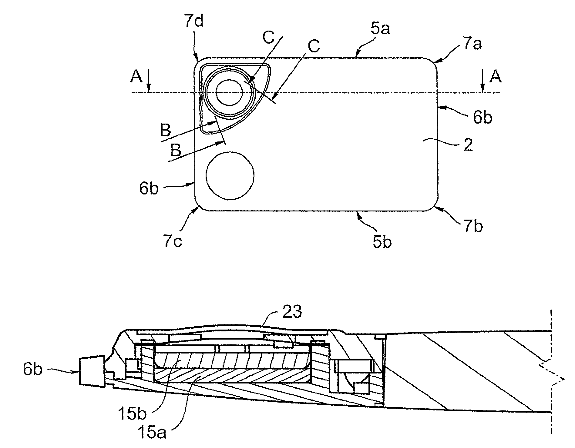
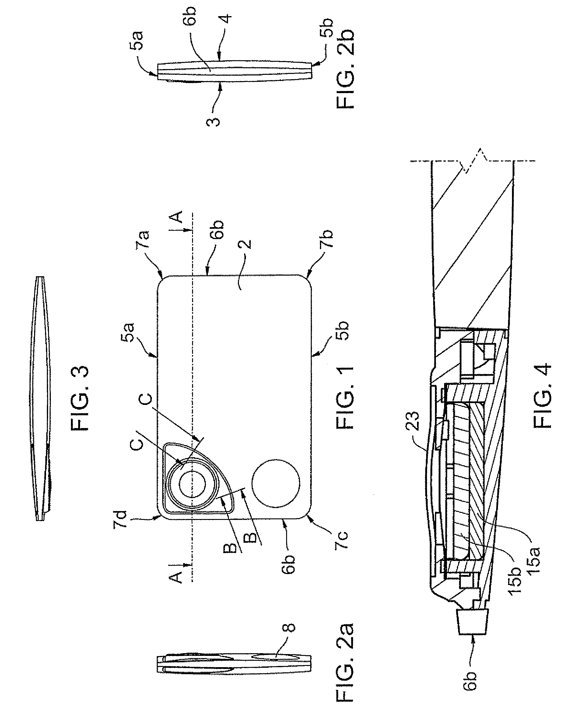
[0024]Referring to the drawings, a pocket magnifier device 1 includes a magnifying lens 2 with opposing convex optical surfaces 3, 4. The magnifying lens 2 is generally of a rectangular card-shape, its periphery including long and short pairs of opposing edge faces 5a, 5b, 6a, 6b joined by radiused corners 7a-7d. Integrally formed in the magnifying lens 2 adjacent corner 7c is a second magnifying optic 8.

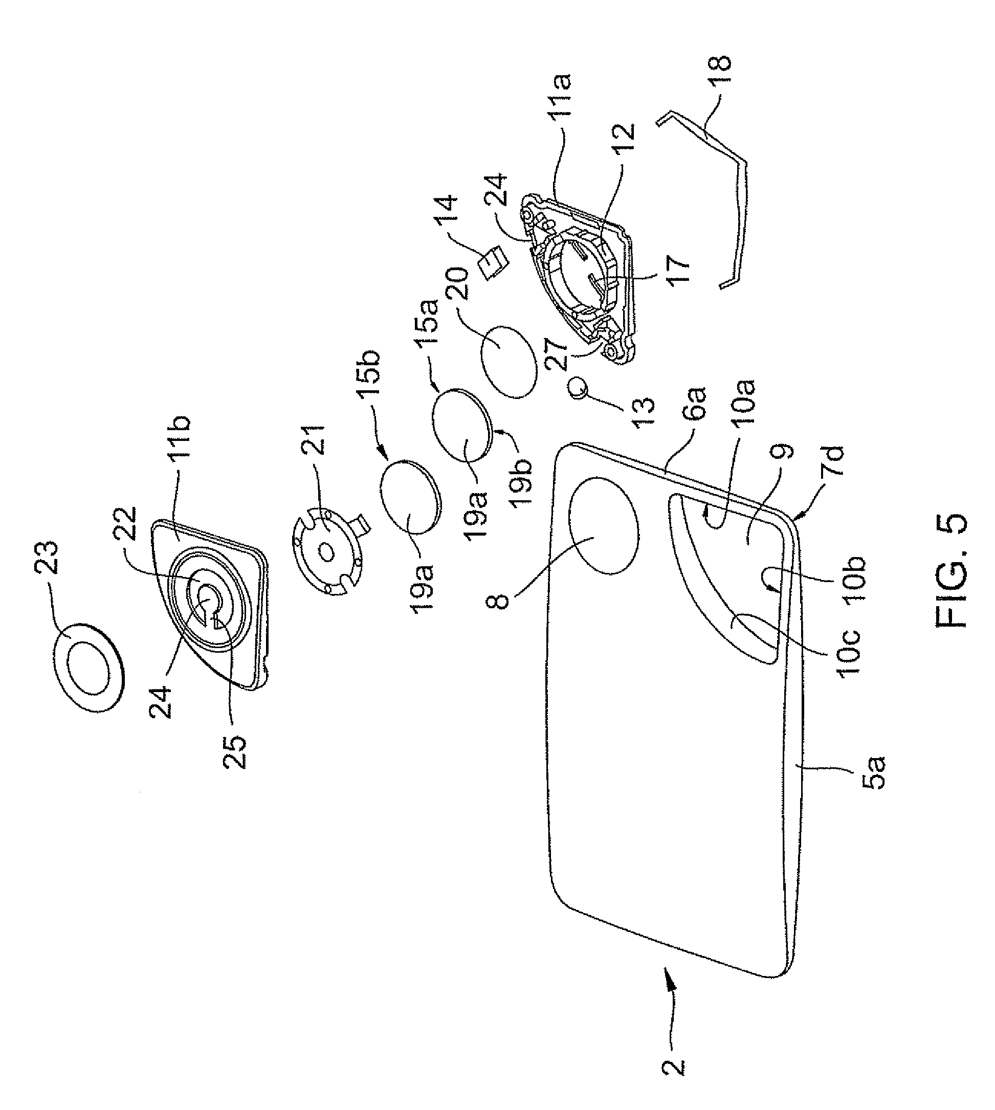
[0025]Proximate the corner 7d is a recess 9 in the lens 2 extends between the optical surfaces 3, 4. The recess 9 bounded by a border surface 10 joining the opposite optical surfaces 3, 4 and including portions 10a, 10b generally parallel to the edges faces 6a, 5a respectively, and subtended by arcuate portion 10c.

[0026]Of complementary shape to, and received within the recess 9, the housing is moulded from opaque polymeric material and includes a housing base 11a and housing top 11b which enclose LEDs 13, 14, two batteries 15a, 15b, pressure-sensitive switch 16 and conductors 17, ...


PUM


Abstract

A card-shaped pocket magnifier device includes a magnifying lens having a pair of opposite optical surfaces. A housing disposed in a recess in the lens, or within a card-shaped envelope of the device, encloses LEDs, a battery and a switch connected by an electrical circuit. The LEDs direct light both edgewise into the lens, for illuminating the lens itself, and away from the lens to illuminate the field of view.

Description

TECHNICAL FIELD[0001]The present invention relates to magnifying devices for use in low ambient light levels.BACKGROUND OF THE INVENTION[0002]For everyday use, many people find it convenient to carry a small magnifying glass in a wallet or pocket so that it can be readily accessed as needed, normally to assist with reading. However, these magnifying glasses have reduced utility in low ambient light levels.[0003]In the manufacture and repair of small mechanical items, and in other specialist areas, magnifying glasses with illumination sources are used. These include magnifying glasses carrying a halogen lamp for illuminating the viewing field. The major disadvantage of these products include the relatively large dimensions, as well as the high heat evolution from the halogen lamp and high electric power requirements for their operation so that either only stationary power supply devices with no mobility or battery-operated power supply units which are heavy can be used.[0004]While a ...

Claims


Application Information

Patent Timeline
IPC IPC(8): G02B27/02G02B7/02
CPCG02B25/02
Inventor CHAM, KIN SHING
Owner GREAT WALL OPTICAL PLASTIC WORKS
Why Eureka
Try Eureka