

Electric hair straightening and waving iron
- Summary
- Abstract
- Description
- Claims
- Application Information
AI Technical Summary
Benefits of technology
Problems solved by technology
Method used
Image

Examples
first embodiment
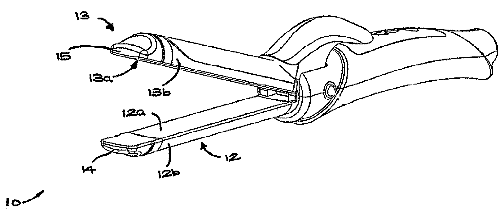
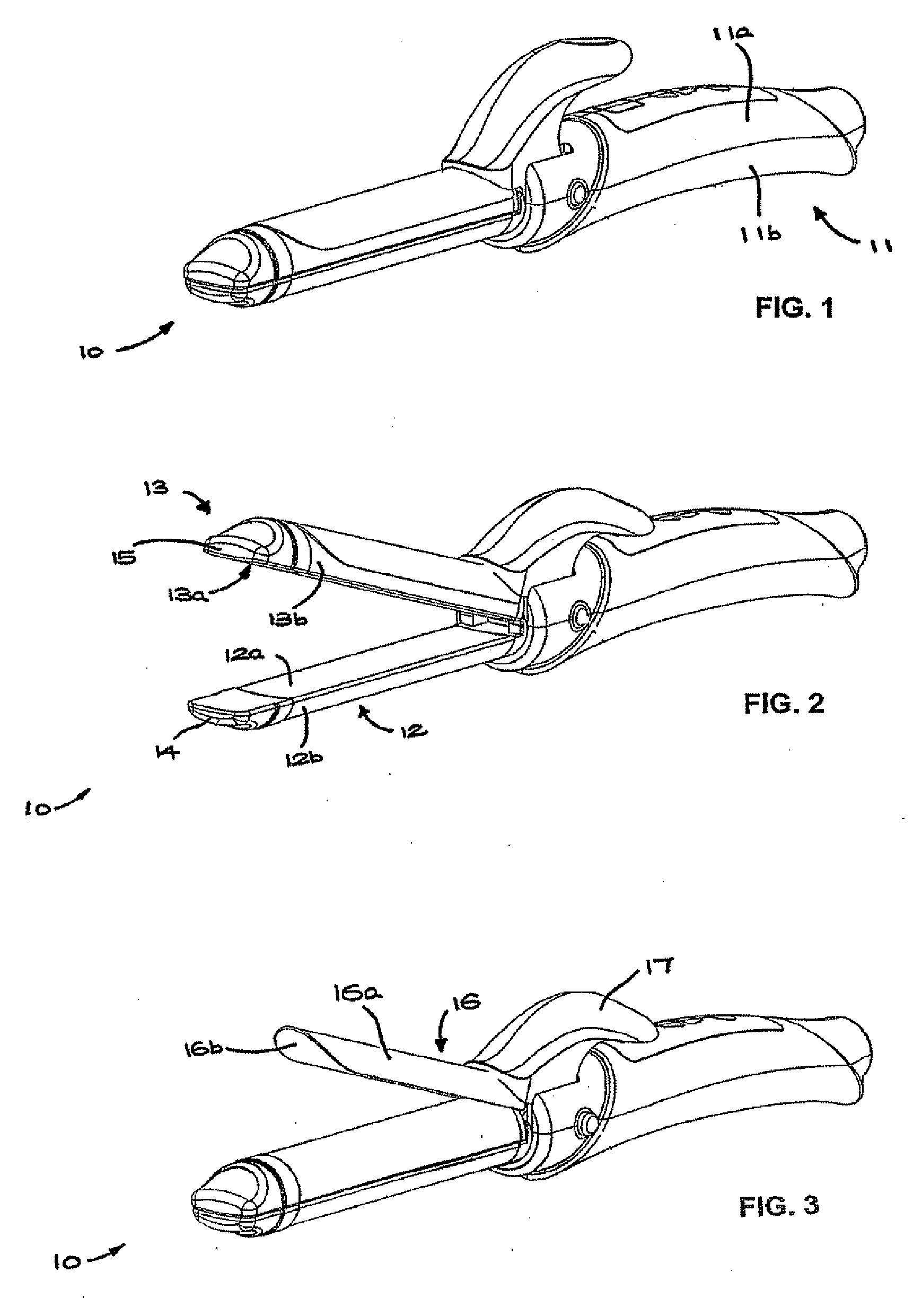
[0039]Referring to FIGS. 1-9, an electric hair styling iron 10 comprises a handle 11 having a convex cross-section and formed from upper and lower elongate shell mouldings 11a, 11b. A power cord (not shown) may extend from the end of the handle 11.
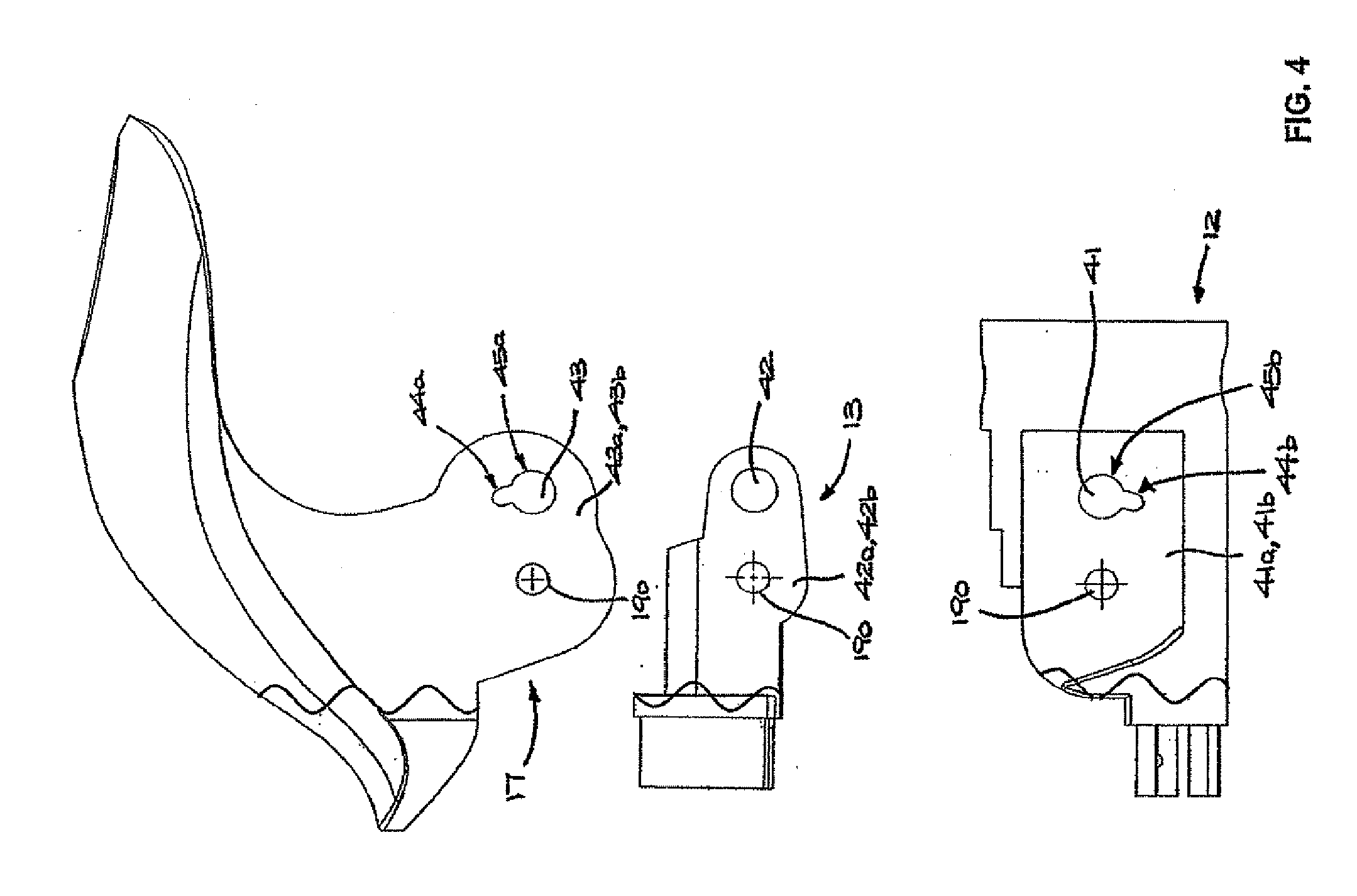
[0040]A first jaw 12 is rigidly fixed to the handle 11 and has flat inner surface 12a and cylindrical outer surface 12b. A second jaw 13, also having flat inner surface 13a and cylindrical outer surface 13b, is attached by a transversely extending pivot 190 to the handle 11 such that the inner faces 12a, 13a are facing one another. Both jaws 12, 13 are elongate and hollow, their distal ends being closed by tips 14, 15 respectively, made of thermally insulating material.
[0041]A hair waving clamp 16 has a clamp portion 16a with concave cylindrical clamp face 16b shaped to conform to the cylindrical face 13b. The clamp 16 is attached by the pivot 190 to the handle 11. A lever portion 17 extends from the clamp portion 16a to the opposite side ...
second embodiment
[0050]an electric hair styling iron 100 is shown in FIGS. 10-18, and like numbers are used to refer to like components. Iron 100 comprises a handle 11 having a convex cross-section and formed from upper and lower elongate shell mouldings 11a, 11b. A power cord (not shown) may extend from the end of the handle 11.
[0051]A first jaw 12 is rigidly fixed to the handle 11 and has flat inner surface 12a and cylindrical outer surface 12b. A second jaw 13, also having flat inner surface 13a and cylindrical outer surface 13b, is attached by a transversely extending pivot 190 to the handle 11 such that the inner faces 12a, 13a are facing one another. Both jaws 12, 13 are elongate and hollow, their distal ends being closed by tips 14, 15 respectively, made of thermally insulating material.
[0052]A hair waving clamp 16 has a clamp portion 16a with concave cylindrical clamp face 16b shaped to conform to the cylindrical face 13b. The clamp 16 is attached by the pivot 19 to the handle 11. A lever po...
PUM
 Abstract
Description
Claims
Application Information