Rotating mechanism of biaxial hinge and portable telephone with the same

a technology of rotating mechanism and hinge, which is applied in the direction of wing accessories, manufacturing tools, instruments, etc., can solve the problems of difficult to answer a call quickly, and achieve the effects of reducing assembly, reducing the restriction of the rotational range, and being more compa

Active Publication Date: 2008-03-18
MITSUBISHI STEEL MFG CO LTD +1
View PDF25 Cites 19 Cited by
  • Summary
  • Abstract
  • Description
  • Claims
  • Application Information

AI Technical Summary

Benefits of technology

[0006]It is an object of the present invention to provide a hinge component that achieves durability, good tactile feedback, smaller size and more lightweight, and simple wiring, for use in a notebook computer or a portable telephone that needs to be smaller and more lightweight.

Problems solved by technology

A portable telephone equipped with a conventional hinge having high rotational torque requires considerable effort to turn, making it difficult to answer a call quickly.

Method used


Image

  • Rotating mechanism of biaxial hinge and portable telephone with the same
  • Rotating mechanism of biaxial hinge and portable telephone with the same
  • Rotating mechanism of biaxial hinge and portable telephone with the same

Examples


first embodiment

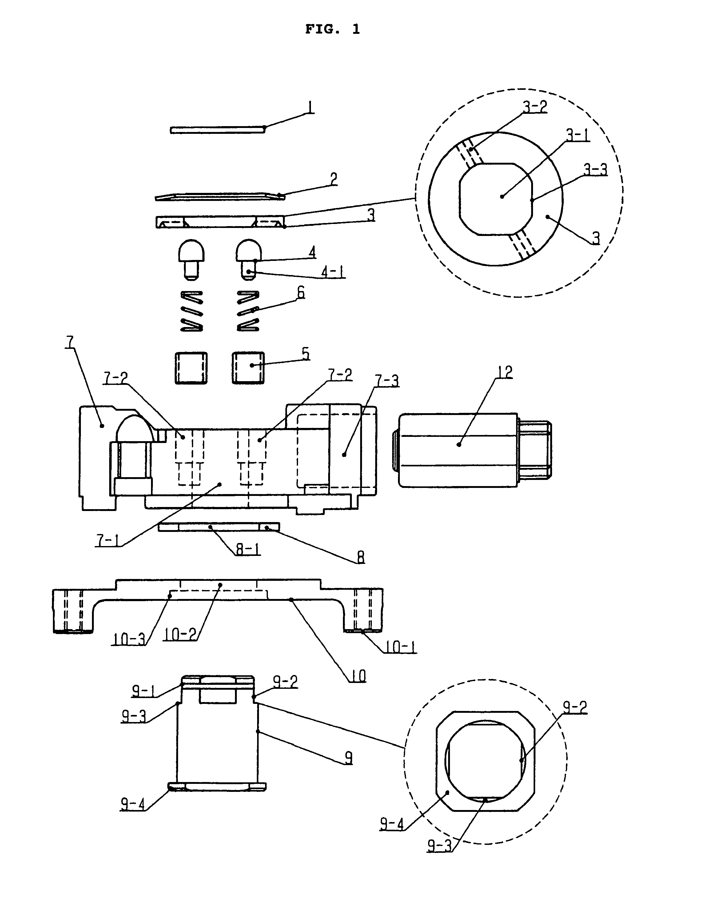
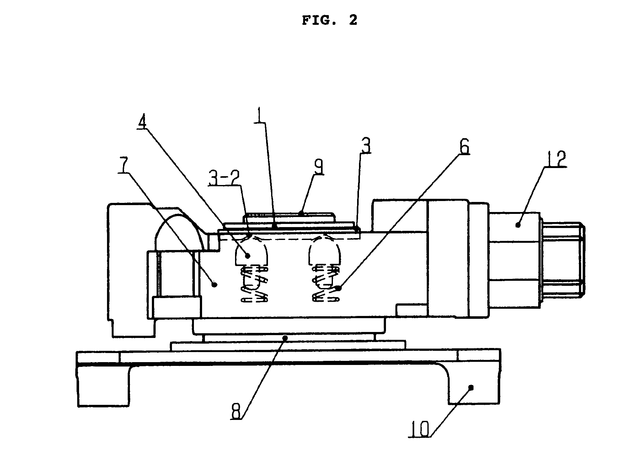
[0029]FIG. 1 illustrates the constitution of the parts pertaining to the first embodiment for the biaxial hinge of the present invention. The rotation system comprises, from the top of the drawing, a snap ring 1, a spring seat 2, a sliding member 3, a pair of pressing components 4 that are substantially spherical in shape at one end, sleeves 5, coil springs 6 as the elastic body, a rotation-side member 7, a lubrication plate 8, a rotating shaft member 9, and a rotating shaft support member 10. That shows the structure in which an opening / closing torque unit mechanism 12 that is a mechanism for opening and closing operations is attached and fixed by insertion into the rotation-side member 7.

[0030]The sliding member 3 is formed by metal stamping so that the outer periphery is circular in shape, and a square hole 3-1 is provided in the center part. The square hole 3-1 of the sliding member 3 accepts the insertion of an end 9-2 of the rotating shaft member 9, so that the sliding member ...

second embodiment

[0043]FIG. 3 shows the constitution of the parts pertaining to the second embodiment for the biaxial hinge of the present invention. The sliding member 3 is closely fixed to the rotating shaft member 9, and the grooves 3-2 are disposed facing upward. The pressing members 4, the sleeves 5, and the coil springs 6 are disposed on the lower side of the rotation-side member 7, and are fixed by a fixing ring 11 and the snap ring 1 via the lubrication plate 8. The provision of the lubrication plate 8 takes into account the friction between the fixing ring 11 and the rotation-side member 7, and can be omitted according to the durability, torque, rotational feel, and so forth required by the biaxial hinge.

[0044]By the present invention, the structure of the upper and lower sides of the rotation-side member 7, that is, the portion that generates the rotational torque, of the examples shown in FIG. 1 illustrating the first embodiment and FIG. 3 illustrating the second embodiment, respectively,...

sixth embodiment

[0047]FIG. 6 is an example of a stopper mechanism on the rotation side of the biaxial hinge in the This drawing shows a side and the bottom of the rotation-side member 7, and a side and the top of the rotating shaft support member 10. When the rotation-side member 7 rotates, a protruding stopper 7-4 of the rotation-side member 7 comes into contact with two protruding stoppers 10-4 of the rotating shaft support member 10, preventing any further rotation. In this example, a stopper structure in which the protruding stoppers 7-4 and 10-4 allow a range of rotation of 180° is shown. The rotational range required by the biaxial hinge can be altered by varying the number, position, and shape of the protruding stopper 7-4 of the rotation-side member 7 and the protruding stoppers 10-4 of the rotation-side member 7. Since the stoppers are provided to the rotation-side member 7 and to the rotating shaft support member 10 simultaneously when the molding of the parts, a rotation stopper mechani...


PUM


Abstract

A biaxial hinge having a rotating mechanism that realizes durability, a good tactile feedback, smaller size and more lightweight is provided for use in a notebook computer or a portable telephone that needs to be smaller and more lightweight. The biaxial hinge is constituted such that a rotating shaft support member is fixed to a rotational shaft support member, a rotation-side member is inserted and attached to the outer periphery of the rotating shaft member, and an opening / closing torque unit mechanism for opening and closing operations is disposed at the rotation-side member, wherein sliding friction torque and click torque are generated by the load produced by a coil spring between pressing members and the rotating shaft support member or a sliding member attached to the rotating shaft member. The rotating mechanism of the biaxial hinge of the present invention affords good durability, a good tactile feedback, and a reduction in size and weight. And, this rotating mechanism is applied to a portable telephone.

Description

FIELD OF THE INVENTION[0001]This invention relates to a biaxial hinge component that is used in the folding and rotating mechanism parts of electrical devices such as portable telephones, notebook computers, electronic organizers, DVD monitors, and remote controls.BACKGROUND OF THE INVENTION[0002]Nearly all of the mechanisms to generate sliding friction torque or click torque with the rotating shaft of a conventional biaxial hinge generate this torque in ways: a corrugated spring is directly held against a sliding member, or a cam is held down with a coned disk spring or other such leaf spring (see Japanese Patent Publication 2002-155923).[0003]FIG. 10 illustrates an example of a conventional biaxial hinge structure. A leaf spring 103 formed in a corrugated shape is attached to one end of a rotating shaft 102 disposed through a stamped opening / closing shaft 101, fixing members 104 are rotatably attached to the both ends of an opening / closing shaft, and rotational torque is generated...

Claims


Application Information

Patent Timeline
Patent Type & Authority Patents(United States)
IPC IPC(8): H04M1/00F16C11/04E05D3/10E05D11/10H04M1/02
CPCH04M1/0212E05D3/10E05D11/1064E05D11/1078Y10T16/1873Y10T16/53864E05Y2900/606G06F1/1622G06F1/1681H04B1/38F16C11/04
Inventor SATO, HITOSHIMITSUI, YASUHIROHIGANO, SAKAEKOSUGI, SATOSHIYAMAGUCHI, KATSUMASASAKAMOTO, KENICHI
Owner MITSUBISHI STEEL MFG CO LTD
Why Eureka
Try Eureka