Holders for prosthetic aortic heart valves

a prosthetic aortic heart valve and a technology for aortic valves, applied in the field of medical devices, can solve the problems of increasing the potential for puncture of one leaflet or improper suturing, precious little space, and difficulty in suturing the sewing ring to surrounding tissue, so as to facilitate valve implantation and reduce the effect of bulkyness and reduced shap

Active Publication Date: 2010-10-05
EDWARDS LIFESCIENCES CORP
View PDF31 Cites 10 Cited by
  • Summary
  • Abstract
  • Description
  • Claims
  • Application Information

AI Technical Summary

Benefits of technology

[0010]The present invention provides an aortic valve holder for flexible leaflet valves that is significantly reduced in shape so as to facilitate valve implantation. The holder of the present invention is less bulky than earlier holders and minimizes obstructions to vision and working space around the valve to facilitate implantation thereof. The holder desirably connects directly and exclusively to tips of the commissures of the aortic heart valve for better tactile feedback during delivery. The legs are sized so that they do not overlap the commissure tips and therefore provide more space between the commissures and the wall of the aortic root to facilitate suture tie-down. The holder has no moving parts to minimize costs and may be molded into a variety of elegant shapes.
[0012]In a preferred embodiment, the prosthetic aortic heart valve has flexible leaflets. Further, the prosthetic aortic heart valve is constructed with a fabric-covered inner stent member that extends up the commissure posts to the commissure tips. The holder legs project radially outward to contact the commissure tips at the radial location of the inner stent member but not as far as the outer radial extent of the commissure posts so as to provide greater space around the commissure posts and minimize obstructing the view of the inflow end of the valve during implantation. The commissure tips are fabric-covered and have a rounded configuration, and an inflow side of the outer ends of each of the holder legs has a concave configuration to match the rounded commissure tips.
[0013]Preferably, the outer end of each of the legs has valve attachment structure and a first width as seen in axial plan view. Each of the legs further includes a mid-section extending between the central hub and the outer end that has a total material width as seen in axial plan view that is less than 50% (preferably less than 33%) of the first width for enhanced visibility of the valve. In one embodiment, each of the legs has a single member mid-section narrower than the outer ends. In another embodiment, each of the legs has a mid-section that is split into two slim rails that are joined together at the outer end, wherein a radial gap is formed between the rails enabling direct axial viewing of the heart valve leaflet free edges therethrough. Each of the legs may have an axial component so as to vault the central hub away from the heart valve.
[0014]The present invention also provides a prosthetic heart valve holder comprising a central hub defining a central axis and a plurality of elongated legs projecting outwardly from an inflow end of the hub. Each of the legs terminates at an outer end having valve attachment structure and a first width as seen in axial plan view. An elongated mid-section extending between the central hub and the outer end of each leg has a total material width as seen in axial plan view that is less than 50% of the first width for enhanced visibility of a valve secured to the holder.
[0017]A more secure engagement between the central hub and a delivery handle is also provided to ensure the holder / handle connection does not become loose during suture placement through the sewing ring. Preferably, fewer handle revolutions are required to screw in and unscrew the handle from the holder.

Problems solved by technology

The holder as well as the upwardly projecting commissure posts can obstruct the surgeon's access to the valve base, making suturing of the sewing ring to surrounding tissue and tying-off of the implanting sutures difficult.
Bulky holders may actually increase the potential for puncture of one of the leaflets or improper suturing.
Even with such an elaborate procedure, there is precious little space between the upstanding commissures and leaflets of the valve and the surrounding aortic wall for the surgeon to manipulate forceps to tie off the sutures.
This is particularly evident in patients having a relatively small aortic root, and is exacerbated by bulky holders.
The Eberhardt holder is relatively complicated, however, and adds cost to the valve.

Method used


Image

  • Holders for prosthetic aortic heart valves
  • Holders for prosthetic aortic heart valves
  • Holders for prosthetic aortic heart valves

Examples


Embodiment Construction

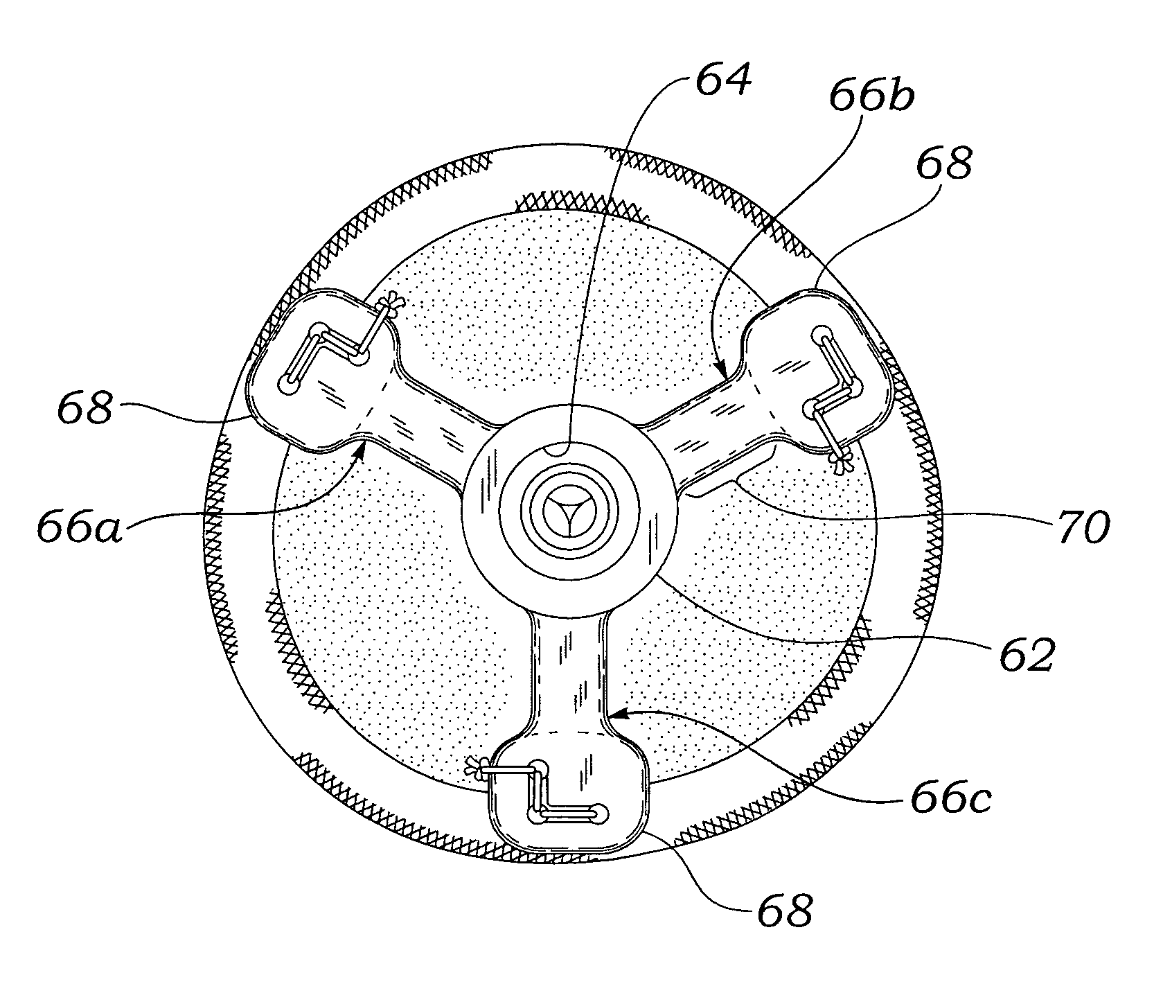
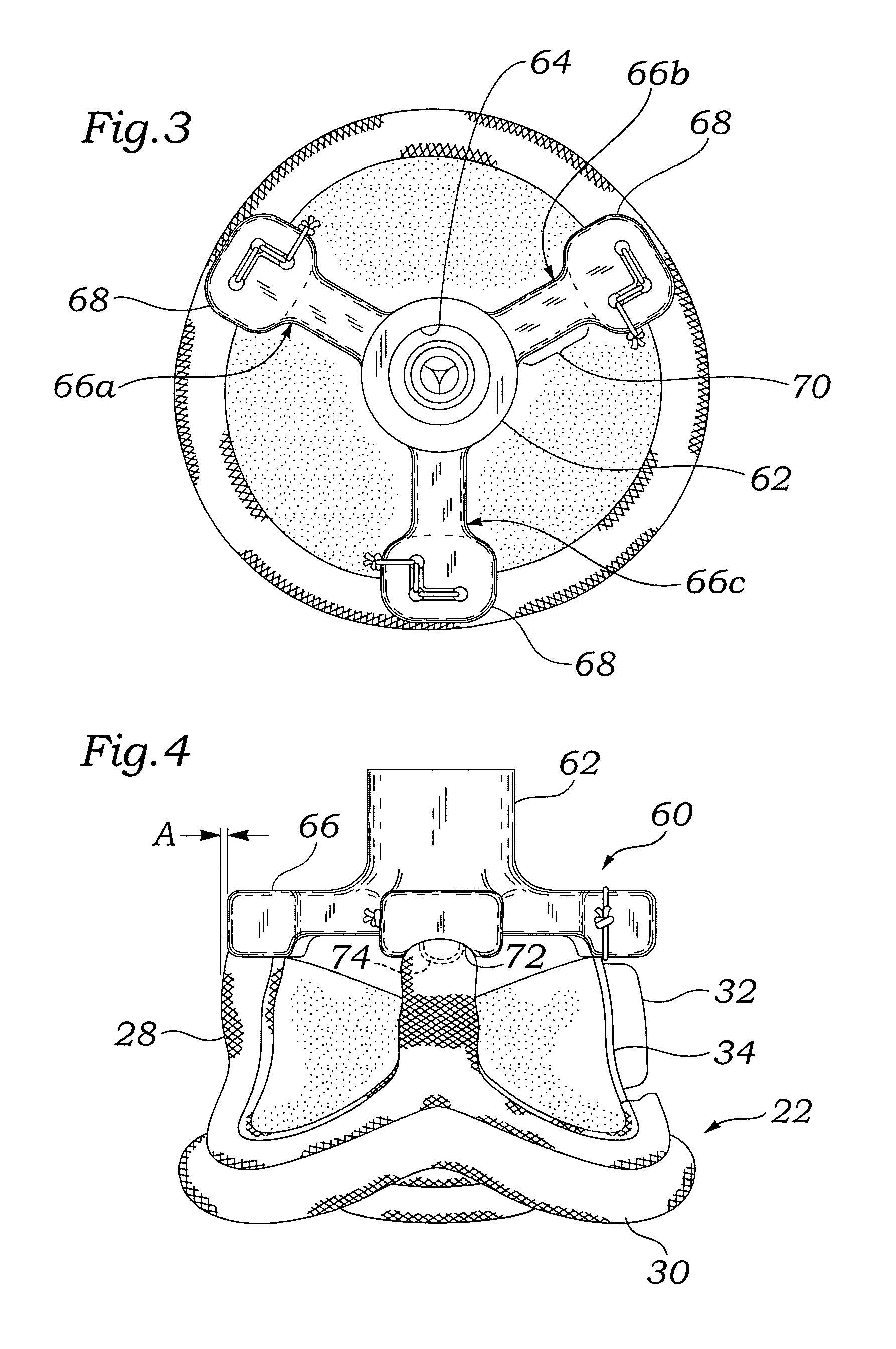
[0024]The present invention provides an improved holder for prosthetic aortic heart valves, in particular flexible leaflet valves. It should be understood, however, that certain features of the holder of the present invention are equally applicable to delivering prosthetic aortic heart valves that have rigid leaflets. Namely, the holders of the present invention attach only to the commissure tips of the valve and provide enhanced visibility of the leaflets and outer extent of the valve, especially the peripheral sewing ring on the inflow end. Such an advantage may also be desirable when implanting mechanical valves.

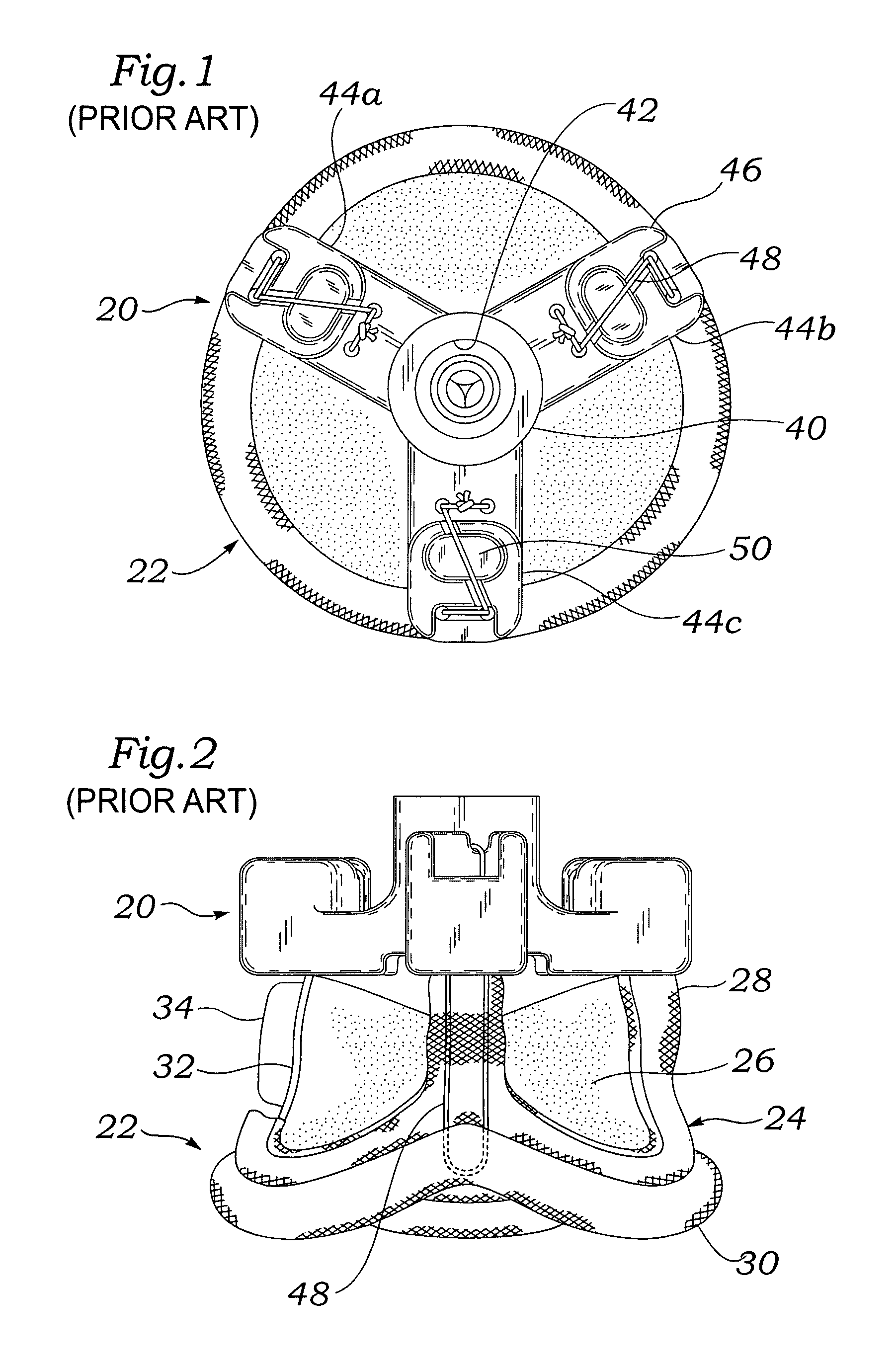
[0025]Is important to review modifications made to an existing aortic valve holder to fully understand the benefits of the present invention. FIGS. 1 and 2 show an existing holder 20 of the prior art attached to the outflow end of a prosthetic aortic valve 22. There are many designs for prosthetic aortic valves in the art, the one shown being the Carpentier-Edwards PERIMO...


PUM


Abstract

A holder for a flexible leaflet prosthetic aortic heart valve that is less bulky than earlier holders and minimizes obstructions to vision and working space around the valve to facilitate implantation thereof. The holder may have a central hub and three outwardly extending legs that connect directly and exclusively to tips of the commissures of the aortic heart valve for better tactile feedback when parachuting and seating the valve in the annulus. The legs are sized so that they do not overlap the commissure tips and therefore afford a better view of the sewing ring adjacent the commissures. The legs may be narrow in the midsection or split into two rails to increase visibility of the valve leaflets. The hub may be vaulted axially upward relative to the outer ends of the legs to further increase visibility of the valve. A more secure engagement between the central hub and a delivery handle is also provided to ensure the holder / handle connection does not become loose during suture placement through the sewing ring and fewer handle revolutions are required to screw in and unscrew the handle from the holder.

Description

FIELD OF THE INVENTION[0001]The present invention relates generally to medical devices, and more particularly to a holder that facilitates the implantation of a flexible leaflet prosthetic aortic heart valve, and associated methodology.BACKGROUND OF THE INVENTION[0002]In mammalian animals, the heart is a hollow muscular organ having four pumping chambers: the left and right atria and the left and right ventricles, each provided with its own one-way valve. The natural heart valves are identified as the aortic, mitral (or bicuspid), tricuspid and pulmonary valves, and each has leaflets to control the directional flow of blood through the heart. The valves are each supported by an annulus that comprises a dense fibrous ring attached either directly or indirectly to the atrial or ventricular muscle fibers. Various surgical techniques may be used to repair a diseased or damaged valve. In a valve replacement operation, the damaged leaflets are often excised and the annulus sculpted to rec...

Claims


Application Information

Patent Timeline
Patent Type & Authority Patents(United States)
IPC IPC(8): A61F2/06
CPCA61F2/2427A61F2/2412
Inventor STOBIE, ROBERT
Owner EDWARDS LIFESCIENCES CORP
Why Eureka
Try Eureka