Inverter circuit for discharge lamps for multi-lamp lighting and surface light source system

a technology of surface light source and discharge lamp, which is applied in the direction of fixed installation, lighting and heating apparatus, instruments, etc., can solve the problems of inability to put the current balancer into practical use as a single device, the current balancer cannot be easily adjusted, and the current balancer is not suitable for single use. , to achieve the effect of reducing the cross-sectional area of the core, reducing the amount of heat generated by saturation, and reducing the step-up transformer or control circui

Inactive Publication Date: 2007-10-16
MASAKAZU USHIJIMA +1
View PDF40 Cites 25 Cited by
  • Summary
  • Abstract
  • Description
  • Claims
  • Application Information

AI Technical Summary

Benefits of technology

[0054]The present invention solves problems peculiar to the inverter circuit for cold-cathode fluorescent lamps by applying shunt transformers conventionally used for hot-cathode lamps to cold-cathode fluorescent lamps, and provides lots of advantageous effects, by combining shunt transformers with cold-cathode fluorescent lamps.
[0055]Further, the shunt transformer itself is entrusted with the operation of causing lighting of unlighted ones of cold-cathode fluorescent lamps when part(s) of the cold-cathode fluorescent lamps is / are unlighted due to reduction of the cross-sectional area of the core of a shunt transformer, by configuring such that the shunt transformer has a large reactance, whereby all the cold-cathode fluorescent lamps are uniformly lighted, and at the same time the currents are caused to be balanced with each other.
[0056]Still further, when the core of a shunt transformer is saturated, a pulsed and distorted high voltage waveform including a harmonic component is generated at a coil terminal on the unlighted side. By making use of this phenomenon, even when the slope of the negative resistance of a discharge lamp is large, all the cold-cathode fluorescent lamps are caused to be lighted, and at the same time the currents are caused to be balanced with each other.
[0057]Further, by actively allowing the saturation of the core, which has been conventionally regarded as harmful, it is possible to downsize the shape of the shunt transformer to its limit.
[0058]Further, by actively allowing the saturation of the core, and at the same time reducing the cross-sectional area of the core, the amount of heat generated by the saturation is reduced.
[0059]As described above, by providing transformers for shunting current in a secondary circuit of the step-up transformer of the inverter circuit, it is possible to shunt the output of the step-up transformer, simultaneously light two or more discharge lamps, and at the same time cause the currents to be balanced with each other, whereby it is made possible to drastically reduce the step-up transformer or a control circuit, or both of them, thereby realizing reduction of costs.

Problems solved by technology

Further, the impedance of hot-cathode lamps is very low, and the discharge voltage thereof is approximately 70 V to several hundreds of volts, which makes it unnecessary to pay much attention to the adverse influence of parasitic capacitance generated around each discharge lamp.
Further, in this method, when one of the connected hot-cathode lamps is unlighted, an excessive voltage is generated at a terminal of a current balancer associated with the unlighted hot-cathode lamp, so that when hot-cathode lamps are partially unlighted, there is no other choice but to interrupt the circuit.
Accordingly, the current balancer could not be put into practical use as a single device unless several countermeasures to the problem are taken beforehand.
Moreover, the current balancer itself was conventionally large in size.
However, many of the proposals which have been made are unstable, and no example of practical use has appeared for a long time period since the early days of the cold-cathode fluorescent lamp.
Further, although the application of the current balancers to cold-cathode fluorescent lamps was experimentally possible, the size of the current balancer was too large for practical use.
Therefore, so long as the inductance is determined based on the theory, an inductance value required for the current balancer has to become excessive, and further, the current balancer inevitably has to be made fairly large in outside dimensions.
However, this results in increased distributed capacitance, thereby causing a decrease in the self-resonance frequency of the current balancer, so that the current balancer loses its reactance.
This can lead to degradation of current-balancing capability of the current balancer.
As a result, the current balancer cannot properly shunt current so that the imbalance of currents is caused.
However, originally, the negative resistance characteristic of each cold-cathode fluorescent lamp in the mounted state is not controlled, and hence e.g. when lots of liquid crystals are changed during mass production, various problems are liable to occur.
Moreover, those skilled in the art have almost no recognition concerning the negative resistance characteristic of the liquid crystal display backlight.
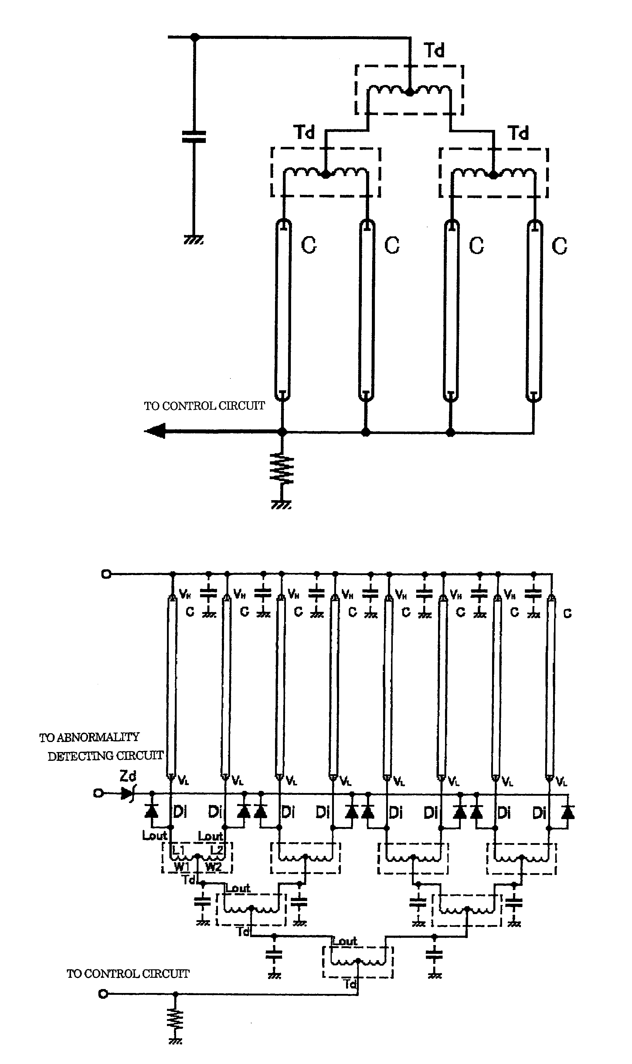
Further, in the example of the conventional current balancer, saturation of the core, which is caused by imbalanced currents in the current balancer, for example, when one of the discharge lamps is unlighted, is regarded as harmful, and hence the saturation is detected by additionally providing a winding in the shunt transformer, for detection of abnormality of the circuit.
If abnormality of the circuit is detected, operation of the circuit is blocked.
When a large number of discharge lamps are to be simultaneously lighted by the conventional inverter circuit for a discharge lamp, the discharge lamps cannot be connected to each other simply in parallel with each other even if they have the same load characteristics.
One of the problems is electrostatic noise irradiated from a conductor having a voltage of 1200 V to 1700 V, which requires electrostatic shielding as a countermeasure against the radiation noise.
Further, the metal ions move along the secondary winding, so that the secondary winding can be sometimes burned due to inter-layer short circuits (layer short circuits) caused by the metal ions.
That is, the continuous application of a high voltage to the secondary winding brings about serious problems concerning the service life and management thereof since the above-described troubles occur as changes due to aging of the products after shipping thereof.
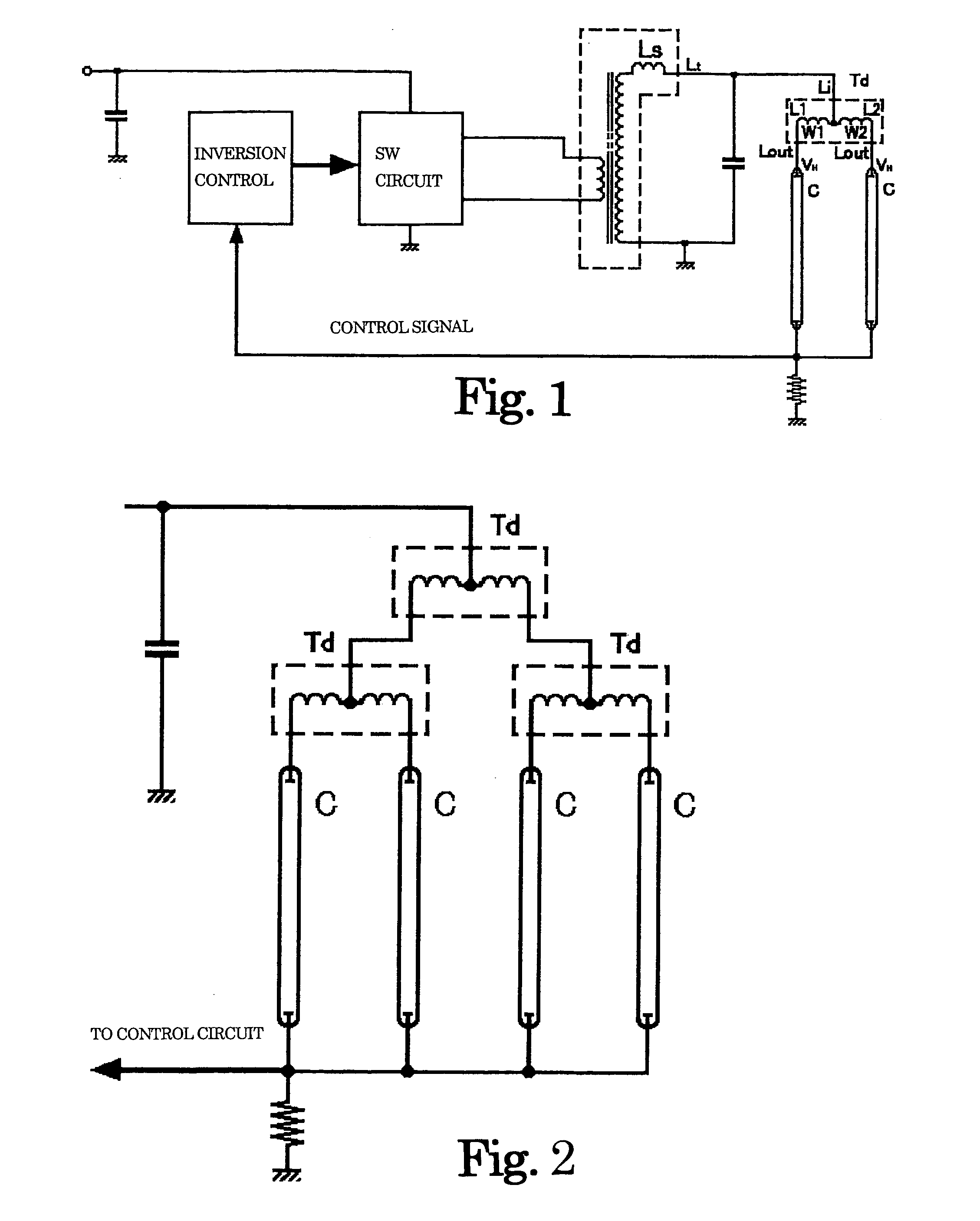
In this method, however, it is necessary to provide a leakage flux transformer and a control circuit for each of cold-cathode fluorescent lamps, which brings about the problems of increases in the circuit size and the manufacturing costs.
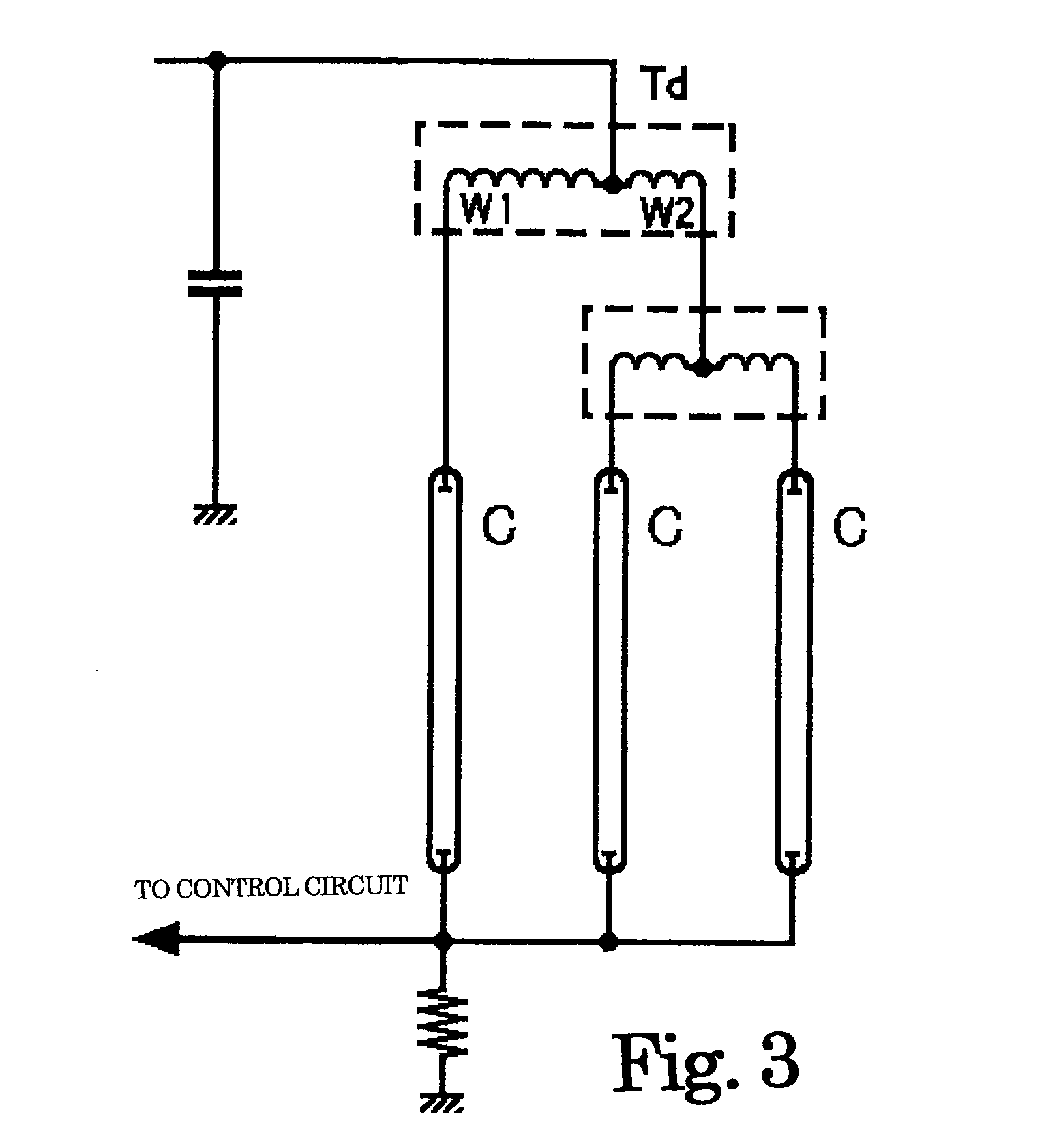
In this method, however, it is not possible to control individual electric currents flowing through a plurality of cold-cathode fluorescent lamps connected to a transformer, so that only one current control can be carried out on the primary winding of the transformer.
Further, when there occurs an imbalance between lamp currents flowing through the cold-cathode fluorescent lamps connected to the secondary windings formed as an assembly, it is almost impossible to make the currents balanced with each other.
Although the above description has been given of the winding transformer, the same problem occurs with an inverter circuit using a piezoelectric transformer.
Therefore, it is not practical to light a plurality of cold-cathode fluorescent lamps by increasing the step-up ratio, and shunting electric current into a plurality of cold-cathode fluorescent lamps using the capacitive ballasts.
Accordingly, in general, one piezoelectric transformer can be connected to only one cold-cathode fluorescent lamp, and hence the use of a piezoelectric inverter circuit has been limited.
When a large number of cold-cathode fluorescent lamps are arranged in parallel for multi-lamp lighting, in most cases, the effect thereof is very unstable, and it sometimes becomes impossible to obtain the shunting and balancing effects all of a sudden, with a different construction of a backlight or a different type of cold-cathode fluorescent lamps.
Further, in the hot-cathode lamp, in general, there is a large voltage difference between a constant discharge voltage and a discharge starting voltage, and particular operation is required at the start of discharge.
Therefore, the problem of continuous application of a high voltage to the secondary winding is not alleviated.
However, those skilled in the art have not recognized the necessity of controlling such a negative resistance characteristic from the early days of the liquid crystal display backlight up to the present time, so that an adequate reactance value that guarantees a stable shunting effect is obscure.
Further, reduction of the size of a shunt transformer based on the excessively set reactance value makes the self-resonance frequency of the shunt transformer too low, which impairs the effect of reactance related to shunting, so that the shunting effect is lost.
However, the protecting means has no operation or effect of protecting the shunt transformer itself.
Further, the conventional method of detecting abnormality is based on detection of deformation of the waveform of magnetic flux generated in the current balancer, and a means of the detection is not simple.
Further, to increase the size of the shunt transformer so as to prevent the saturation of the shunt transformer inversely leads to an increase in core loss caused by the saturation of the shunt transformer.
This has caused generation of a considerable amount of heat.
Furthermore, the cold-cathode fluorescent lamp, which has a high constant discharge voltage, is largely influenced by the parasitic capacitance generated in nearby associated circuit components and wiring connected thereto, so that if the parasitic capacitances occurring in wiring between an inverter circuit and cold-cathode fluorescent lamps are different, imbalance in currents flowing through the cold-cathode fluorescent lamps is caused.

Method used


Image

  • Inverter circuit for discharge lamps for multi-lamp lighting and surface light source system
  • Inverter circuit for discharge lamps for multi-lamp lighting and surface light source system
  • Inverter circuit for discharge lamps for multi-lamp lighting and surface light source system

Examples


Embodiment Construction

[0094]The invention will now be described in detail with reference to FIGS. 1 to 15 showing embodiments thereof.

[0095]FIG. 1 is a diagram of a comprehensive embodiment showing the principle of the present invention, in which there are arranged coils L1 and L2 having windings W1 and W2 wound therearound, respectively, on the secondary side of a leakage flux transformer Ls, which is a step-up transformer of an inverter circuit for discharge lamps, and opposed one ends L1 of the coils L1 and L2 are connected to each other, and connected to a secondary winding Lt of the leakage flux transformer Ls. The other ends Lout of the coils L1 and L2 are connected to high voltage terminals VH of cold-cathode fluorescent lamps C, respectively.

[0096]Magnetic fluxes generated by the coils L1 and L2 are connected such that they are opposed to each other, and it is necessary to increase a coupling coefficient to some extent, i.e. to ensure a certain high mutual inductance. When electric currents flowi...


PUM

PropertyMeasurementUnit
discharge voltageaaaaaaaaaa
lengthaaaaaaaaaa

Abstract

An inverter circuit for discharge lamps for multi-lamp lighting in which the value of a negative resistance characteristic of a fluorescent lamp is controlled, and an excessively set reactance is eliminated by causing a shunt transformer to have a reactance exceeding the negative resistance characteristic. Two coils connected to a secondary winding of a step-up transformer of the inverter circuit are arranged and magnetically coupled to each other to form a shunt transformer for shunting current such that magnetic fluxes generated thereby cancel each other out. Discharge lamps are connected to the coils, respectively, with currents flowing therethrough being balanced. Each discharge lamp is lighted because a reactance of an inductance related to the balancing operation which is in an operating frequency of the inverter circuit, exceeds a negative resistance of discharge lamps.

Description

[0001]This application claims priority to Japanese Patent Application Nos. 2003-31808 filed on Feb. 10, 2003, 2003-109811 filed on Apr. 15, 2003 and 2004-003740 filed on Jan. 9, 2004.TECHNICAL FIELD[0002]This invention relates to an inverter circuit for discharge lamps, such as cold-cathode fluorescent lamps and neon lamps, and more particularly to an inverter circuit for discharge lamps for multi-lamp lighting, which includes current-balancing transformers for lighting a large number of discharge lamps, and a surface light source system.BACKGROUND OF THE INVENTION[0003]Recently, backlights for liquid crystal displays have been increased in size, and with the increase in the size of the backlights, a lot of cold-cathode fluorescent lamps have come to be used per each backlight. Also in inverter circuits for liquid crystal display backlights, multi-lamp lighting circuits are used for lighting a large number of cold-cathode fluorescent lamps.[0004]Conventionally, to light a large numb...

Claims


Application Information

Patent Timeline
Patent Type & Authority Patents(United States)
IPC IPC(8): H05B41/24F21V23/02F21S2/00F21S8/04F21Y103/00H01F38/08H05B41/26H05B41/282
CPCH05B41/2822H01F30/04H01F38/10H05B41/26
Inventor USHIJIMA, MASAKAZUKAWAMOTO, KOJIYAMAMOTO, YOUICHIKIJIMA, MINORU
Owner MASAKAZU USHIJIMA
Why Eureka
Try Eureka