Method for producing a mask layout avoiding imaging errors for a mask

a mask and mask technology, applied in the field of mask layout avoiding mask imaging errors, can solve the problems of not being able to meet the predefined geometrical dimensions of the mask structure, imaging errors can occur, and mask layouts may not be produced

Inactive Publication Date: 2008-03-18
POLARIS INNOVATIONS LTD
View PDF22 Cites 188 Cited by
  • Summary
  • Abstract
  • Description
  • Claims
  • Application Information

AI Technical Summary

Benefits of technology

[0016]In one aspect, the invention improves a method of the type specified in the background to the effect that imaging errors, in particular as a result of proximity effects, are avoided even better than before.

Problems solved by technology

It is known that, in lithography methods, imaging errors can occur if the structures to be imaged become very small and have a critical size or a critical distance with respect to one another.
What is more, imaging errors may occur if structures are arranged so closely next to one another that they mutually influence one another during the imaging.
What is disadvantageous in the case of the target OPC variant, however, is that the predefined geometrical dimensions of the mask structures are actually complied with only when the predefined process parameters are complied with in a quasi exact fashion.
This may lead, for example, to a tearing away of lines or to a short circuit between lines.

Method used


Image

  • Method for producing a mask layout avoiding imaging errors for a mask
  • Method for producing a mask layout avoiding imaging errors for a mask
  • Method for producing a mask layout avoiding imaging errors for a mask

Examples


first exemplary embodiment

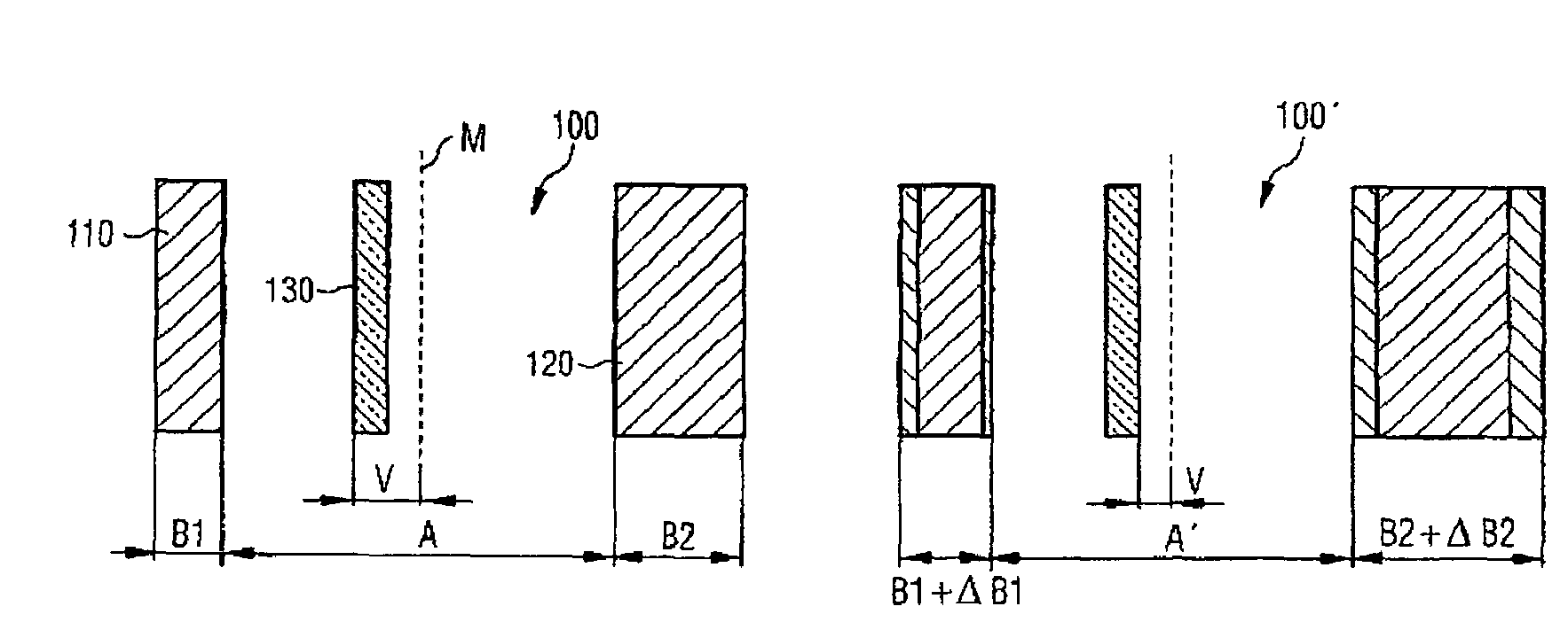
[0123]FIGS. 3A and 3B show, by way of example, the eccentric arrangement according to the invention of optically non-resolvable auxiliary structures (first exemplary embodiment).

[0124]FIG. 3A reveals a provisional auxiliary mask layout 100 comprising two lines (or bars) 110 and 120 arranged at a distance A. The two lines have different structures widths B1 and B2. A scatterbar 130 is added as an optically non-resolvable auxiliary structure between the two lines 110 and 120. As can be discerned in FIG. 3A, the scatterbar 130 is offset by an offset V relative to the centre M between the two bars 110 and 120. The size of offset V is chosen in a manner dependent on the width difference ΔB where

ΔB=B1−B2

and the distance A between the lines and can be gathered for example from the table in FIG. 12. The offset V is thus a function of the following variables:

V=f(ΔB, A)

[0125]As an alternative, the absolute values of the widths may also have an influence in addition. In this case, then, the of...

seventh exemplary embodiment

[0165]In the method, the SRAF auxiliary structures 550 are arranged exclusively in the region of the active layout regions 430′ (see FIGS. 16 and 17). No SRAF auxiliary structures are positioned in the remaining layout regions 440′ (“gate-only” positioning as seventh exemplary embodiment).

eighth exemplary embodiment

[0166]It can be discerned in FIG. 17 that despite the optimization of the mask layout, it is possible for regions 600 to occur in which the inactive layout region 440′ make contact with the active layout regions 430′ after the OPC method has been carried out. These problems may occur in isolated fashion since, as explained above, the inactive layout regions 440′ are processed by means of a defocus OPC method, so that a certain expanding of lines and / or corners occurs. Such regions where contact is made must be detected, if appropriate in the course of an aftertreatment, for example an automatic or manual aftertreatment, and repaired (eighth exemplary embodiment).


PUM


Abstract

A final mask layout (20′) is produced by producing a provisional auxiliary mask layout in accordance with a predefined electrical circuit diagram and converting it into the final mask layout (20′) with the aid of an OPC method. Before carrying out the OPC method, with the provisional auxiliary mask layout (100), firstly a modified auxiliary mask layout (100′) is formed by arranging at least one optically non-resolvable auxiliary structure (130) between two mask structures (110, 120) of the provisional auxiliary mask layout (100). The optically non-resolvable auxiliary structure (130) is positioned between the two mask structures (110, 120) in a manner dependent on the structure size (B1, B2) of the two mask structures, (110, 120). An eccentric offset (V) of the optically non-resolvable auxiliary structure (130) between the two mask structures is effected in the case of differing structure sizes (ΔB) of the two mask structures.

Description

[0001]This application claims priority to German Patent Application 10 2004 047 263.7 which was filed Sep. 24, 2004, and is incorporated herein by reference.TECHNICAL FIELD[0002]The invention relates to a method for producing a mask layout avoiding imaging errors for a mask.BACKGROUND[0003]It is known that, in lithography methods, imaging errors can occur if the structures to be imaged become very small and have a critical size or a critical distance with respect to one another. The critical size is generally referred to as the “CD” value (CD: critical dimension).[0004]What is more, imaging errors may occur if structures are arranged so closely next to one another that they mutually influence one another during the imaging. These imaging errors based on “proximity effects” can be reduced by modifying the mask layout beforehand with regard to the “proximity phenomena” that occur. Methods for modifying the mask layout with regard to avoiding proximity effects are referred to by expert...

Claims


Application Information

Patent Timeline
Patent Type & Authority Patents(United States)
IPC IPC(8): G06F17/50
CPCG03F1/144G03F1/36
Inventor SEMMLER, ARMIN
Owner POLARIS INNOVATIONS LTD
Why Eureka
Try Eureka