Method for producing for a mask a mask layout which avoids aberrations

Inactive Publication Date: 2005-06-02
INFINEON TECH AG
View PDF2 Cites 17 Cited by
  • Summary
  • Abstract
  • Description
  • Claims
  • Application Information

AI Technical Summary

Benefits of technology

[0015] The invention is directed to an improved method of the type specified in the introduction to the ef

Problems solved by technology

It is known that, in lithography methods, aberrations can occur if the structures to be imaged become very small and have a critical size or a critical distance with respect to one another.
However, it is disadvantageous in the case of the target OPC variant that the prescribed geometric dimensions of the mask structures are actually observed only when the prescribed p

Method used


Image

  • Method for producing for a mask a mask layout which avoids aberrations
  • Method for producing for a mask a mask layout which avoids aberrations
  • Method for producing for a mask a mask layout which avoids aberrations

Examples


third exemplary embodiment

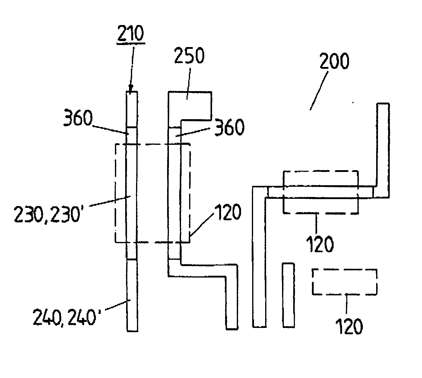
[0077] In the method, the SRAF auxiliary structures 350 are arranged exclusively in the region of the active layout areas 230′ (compare FIGS. 8 and 9). No SRAF auxiliary structures are placed in the remaining layout areas 240′ (gate-only placement as third exemplary embodiment).

fourth exemplary embodiment

[0078] It is to be seen in FIG. 9 that despite the optimization of the mask layout it is possible in accordance with the OPC step for areas 400 to occur in which the inactive layout areas 240′ make contact with the active layout areas 230′. These problems can occur in isolated fashion since—as stated above—the inactive layout areas 240′ are processed with a defocus OPC method such that a certain widening of lines and / or corners results. Such contact areas must be detected, if appropriate in the course of aftertreatment, for example automatic or manual aftertreatment, and repaired (fourth exemplary embodiment).

fifth exemplary embodiment

[0079] It is also to be seen in FIG. 9 that the landing pads 250 are preferably likewise subjected to separate treatment (fifth exemplary embodiment), since it is generally impossible to use conventional self-aligned contacts for landing pads, this being so because landing pads regularly have particular overlay requirements owing to the fact that on the one hand landing pads are not allowed to become too small in order to maintain possible contact, and on the other hand they are not allowed to become too large so as to avoid short circuits (bridging) with adjacent wiring structures. Consequently, a target OPC method is generally to be preferred for landing pads, instead of a defocus OPC method.

[0080] Just like the active layout areas, landing pads can likewise be detected from mask layouts being laid one on top of the other; alternatively, the landing pads can also be detected manually or with the aid of a data processing system by using their typical geometric dimensions or by usin...


PUM


Abstract

A method for producing for a mask a mask layout which avoids aberrations in which a provisional auxiliary mask layout produced, in particular in accordance with a prescribed electrical circuit diagram is converted into the mask layout with the aid of an OPC method. At least two different OPC variants are used in the course of the OPC method by subdividing the original auxiliary mask layout into at least two layout areas and processing each of the layout areas in accordance with one of the at least two OPC variants.

Description

FIELD OF THE INVENTION [0001] The invention relates to photolithographic semiconductor fabrication, and more particularly to methods that use masks to transpose (image) circuit structure features onto a semiconductor wafer. BACKGROUND OF THE INVENTION [0002] It is known that, in lithography methods, aberrations can occur if the structures to be imaged become very small and have a critical size or a critical distance with respect to one another. The critical size is generally referred to as the “CD” value (CD: Critical Dimension). [0003] What is more, aberrations may occur if structures are arranged so closely next to one another that they influence one another reciprocally during imaging; these aberrations based on “proximity effects” can be reduced by modifying the mask layout beforehand with regard to the “proximity phenomena” that occur. Methods for modifying the mask layout with regard to avoiding proximity effects are referred to by experts by the term OPC methods (OPC: Optical...

Claims


Application Information

Patent Timeline
IPC IPC(8): G03F1/00G06F17/50
CPCG03F1/144G03F1/36
Inventor SEMMLER, ARMINTHIELE, JORGMEYNE, CHRISTIANBODENDORF, CHRISTOF
Owner INFINEON TECH AG
Why Eureka
Try Eureka