Manufacturing method of metal-based circuit board of LED

A technology for metal-based circuit boards and manufacturing methods, which is applied in the fields of printed circuit manufacturing, circuit substrate materials, and printed circuit precursor manufacturing, can solve the problems of slow production speed, waste of raw materials, and increased production costs, and achieve strong thermal conductivity. Strong adhesion and high pressure resistance

Active Publication Date: 2016-11-16
ZHEJIANG LEUCHTEK ELECTRONICS
View PDF2 Cites 19 Cited by
  • Summary
  • Abstract
  • Description
  • Claims
  • Application Information

AI Technical Summary

Problems solved by technology

[0003] At present, there are still two researches on the integration of the power drive part and the light source. One of the methods is to place the drive power part in the LED light source circuit directly on the aluminum-based circuit board in the form of a patch, and use AC-AC Driven by this method, the LED lamps made in this way often produce flickering phenomena, and are affected by factors such as the surge of the grid line, the driver chip is easily damaged, and the stability of the LED lamp is seriously affected; another method is Use the milled (or punched) FR4, CEM-1 or CEM-3 board as the substrate, inlay it on the pre-milled (or punched) aluminum plate of the same size, then coat the insulating layer and cover with copper The foil plate is pressed together, and then the circuit board is processed and produced to make an electric light source integrated LED lamp. The disadvantage of this method is that the material cost and processing cost are doubled, and the production efficiency is very low. It can only be manufactured in small quantities and cannot be mass-produced. ; and when pressing, due to the thickness error generated when the power base material and the aluminum plate itself are cut, the error that occurs when the substrate is embedded on the aluminum plate, and th

Method used


Image

  • Manufacturing method of metal-based circuit board of LED
  • Manufacturing method of metal-based circuit board of LED

Examples


Embodiment 1

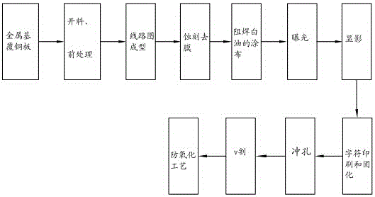
[0029] refer to figure 1 , figure 2 As shown, a method for manufacturing an LED metal-based circuit board usually includes two parts: making a metal-based copper-clad laminate and making a metal-based circuit board based on it. The steps include:

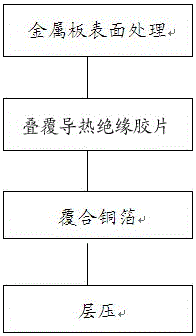
[0030] Manufacture of metal-based copper clad laminates

[0031] (1) Surface treatment of the metal plate: select an aluminum plate with a thickness of 0.2 mm, degrease, roughen, clean, and dry the surface to obtain an aluminum base plate.

[0032] (2) Overlapping thermally conductive insulating film: it is to laminate the thermally conductive insulating film on the aluminum substrate, among which there are three types of insulating adhesive, among which there are three types of insulating adhesive, ① thermally conductive PP composed of glass cloth and thermally conductive adhesive, ② with Ordinary PP composed of glass cloth and epoxy resin, ③ thermally conductive adhesive film composed of thermally conductive adhesive. And the ...

Embodiment 2

[0046] First, a 1.5mm aluminum plate is selected. The step (5) is different from that of Example 1. This example adopts a printing process to realize circuit diagram formation. The UV curing energy on the surface is 650mj to form a pattern on the substrate surface, and then the copper foil surface is printed and UV cured to form a circuit pattern on the surface of the board. Other steps are the same as in Example 1.

[0047] In the present invention, a copper plate with a thickness of 0.1 mm or 0.2 mm can be selected, and the other steps are the same as in Embodiment 2 to manufacture an integrated LED circuit board integrating a driving electric light source.

Embodiment 3

[0049] First, a 1mm aluminum plate is selected, and step (5) is different from Example 1. In this example, a printing process is used to realize circuit diagram formation. The printing process is printed with UV ink. The UV curing energy of the substrate is 800mj to form a pattern on the substrate surface, and then the copper foil surface is printed and UV cured to form a circuit pattern on the substrate surface. The other steps are the same as in Example 1.

[0050] In the present invention, metal substrates such as iron plates or silicon steel plates can also be selected as substrate materials. In step (5), the exposure process is used to realize the formation of circuit diagrams, and other steps are the same as in embodiment 3.


PUM


Abstract

The invention relates to a manufacturing method of a metal-based circuit board of an LED. A finished product is obtained through a metal plate surface treatment step, a heat-conducting insulating film superimposing step, a combined copper foil laminating step, a cutting step, a location hole drilling step, a pretreatment step, a circuit diagram forming step, an etching and stripping step, a solder resist white oil coating step, an exposure step, a developing step, a character printing and solidifying step, a punching step, a v cutting step and an anti-oxidation process. PP glue is combined on a metal-based base plate; and a printing technology or an exposure technology is adopted for circuit diagram forming. Through the technical scheme provided by the invention, the metal-based circuit board integrating a drive power supply and a light source can be massively produced; and the manufactured LED and power supply have good heat dissipation performance.

Description

technical field [0001] The invention relates to the field of LED optoelectronic technology, in particular to a method for manufacturing an LED metal-based circuit board. Background technique [0002] LED lighting fixtures, because the lamp beads will generate heat during the working process, therefore, it is necessary to use a metal-based circuit board with good heat dissipation and heat resistance as the carrier of the LED lamp beads; at the same time, the lamp beads of the LED lamps are in the form of a patch Welding, and the components of the driving power supply need to be welded in the form of plug-ins. Therefore, the driving power and light source of the LED lamp can only be manufactured separately and used in connection, which brings a lot of trouble to production and life, and the material and manufacturing costs are also relatively high. higher. In order to pursue lightness and convenience, people expect to integrate the power drive and light source of the LED illu...

Claims


Application Information

Patent Timeline
IPC IPC(8): H05K3/02H05K3/06H05K1/05
CPCH05K1/056H05K3/022H05K3/06H05K2203/06
Inventor 楼方寿楼红卫
Owner ZHEJIANG LEUCHTEK ELECTRONICS
Why Eureka
Try Eureka