Supercharge Your Innovation With Domain-Expert AI Agents!

Methods and system for inspection of fabricated components

a technology of fabricated components and inspection methods, applied in the direction of mechanical measuring arrangements, instruments, mechanical means, etc., can solve the problems of insufficient repeatability of quality verification purposes, insufficient visual or manual inspection, and insufficient accuracy of modem components

Active Publication Date: 2008-03-25
GENERAL ELECTRIC CO
View PDF24 Cites 4 Cited by
  • Summary
  • Abstract
  • Description
  • Claims
  • Application Information

AI Technical Summary

Benefits of technology

"The patent describes a method, system, and computer program for inspecting components to detect any breaks or damage. The method involves receiving data points that define the shape of the component, fitting them to a curve that defines a predetermined model shape, and comparing them to the curve to determine if there is a break radius. The system includes a fixture for holding the component in a fixed position, a profileometer for tracing the profile of the component, and a controller for comparing the traced profile to the curve to determine if it meets the allowable break radius. The computer program includes a code segment for selecting a profile specification and determining if the component profile is substantially equal to the specification. The technical effects of this patent include improved accuracy and efficiency in inspecting components for damage or breaks."

Problems solved by technology

A knowledgeable and skilled technician may be able to ascertain the worthiness of a particular component for replacement using visual or manual inspection, however visual or manual inspection may not be accurate enough for modem components, nor repeatable for quality verification purposes.

Method used


Image

  • Methods and system for inspection of fabricated components
  • Methods and system for inspection of fabricated components
  • Methods and system for inspection of fabricated components

Examples


Embodiment Construction

[0010]As used herein, the term “component” may include any component configured to be coupled within a gas turbine engine, wherein the component may include dimensional characteristics indicative of component wear and / or failure The turbine blade dovetail illustrated is intended as exemplary only, and thus is not intended to limit in any way the definition and / or meaning of the term “component”. Furthermore, although the invention is described herein in association with a gas turbine engine, and more specifically for use with a rotor for a gas turbine engine, it should be understood that the present invention is applicable to other components, such as gas turbine engine stationary components, and components associated with machines other than gas turbine engines. Accordingly, practice of the present invention is not limited to gas turbine engines.

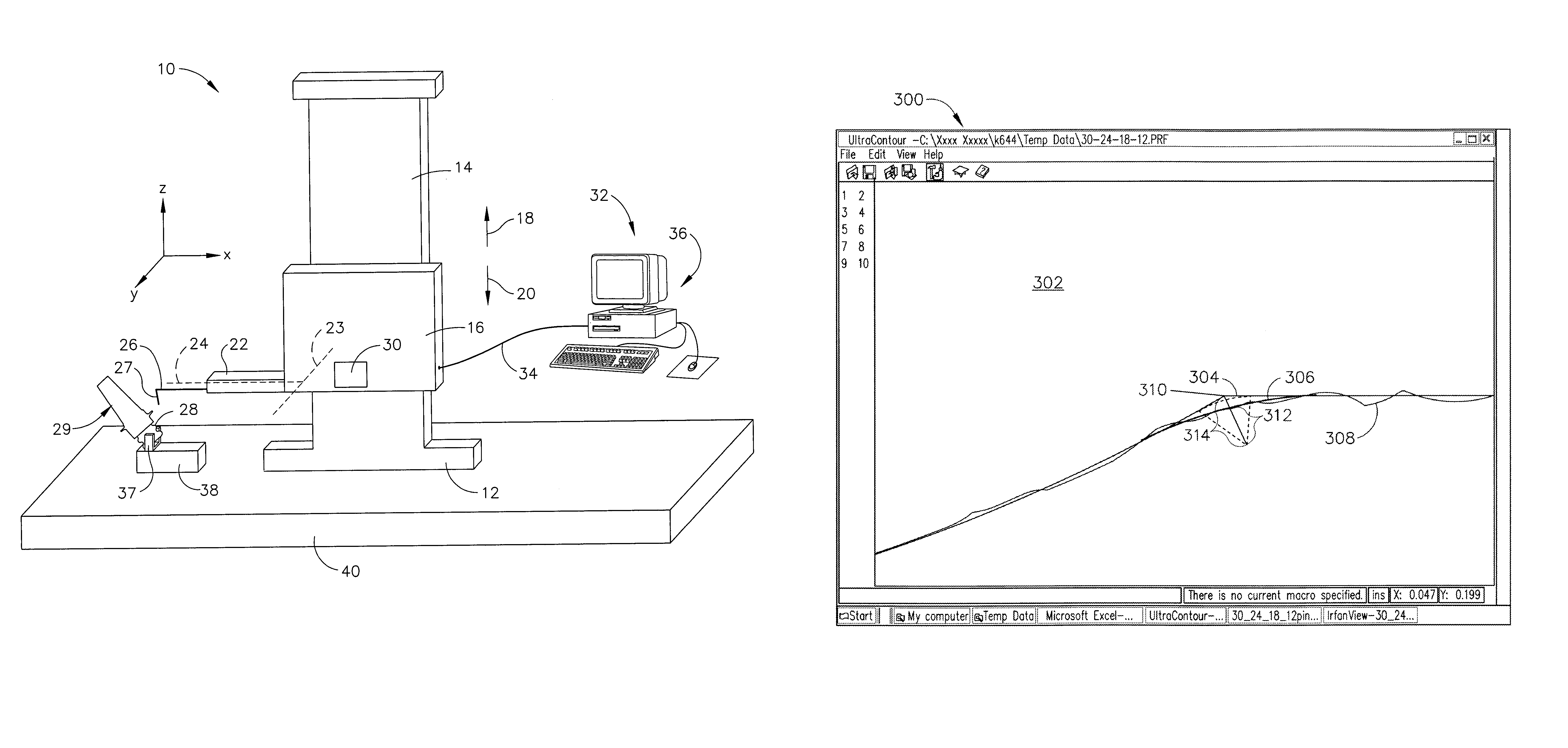
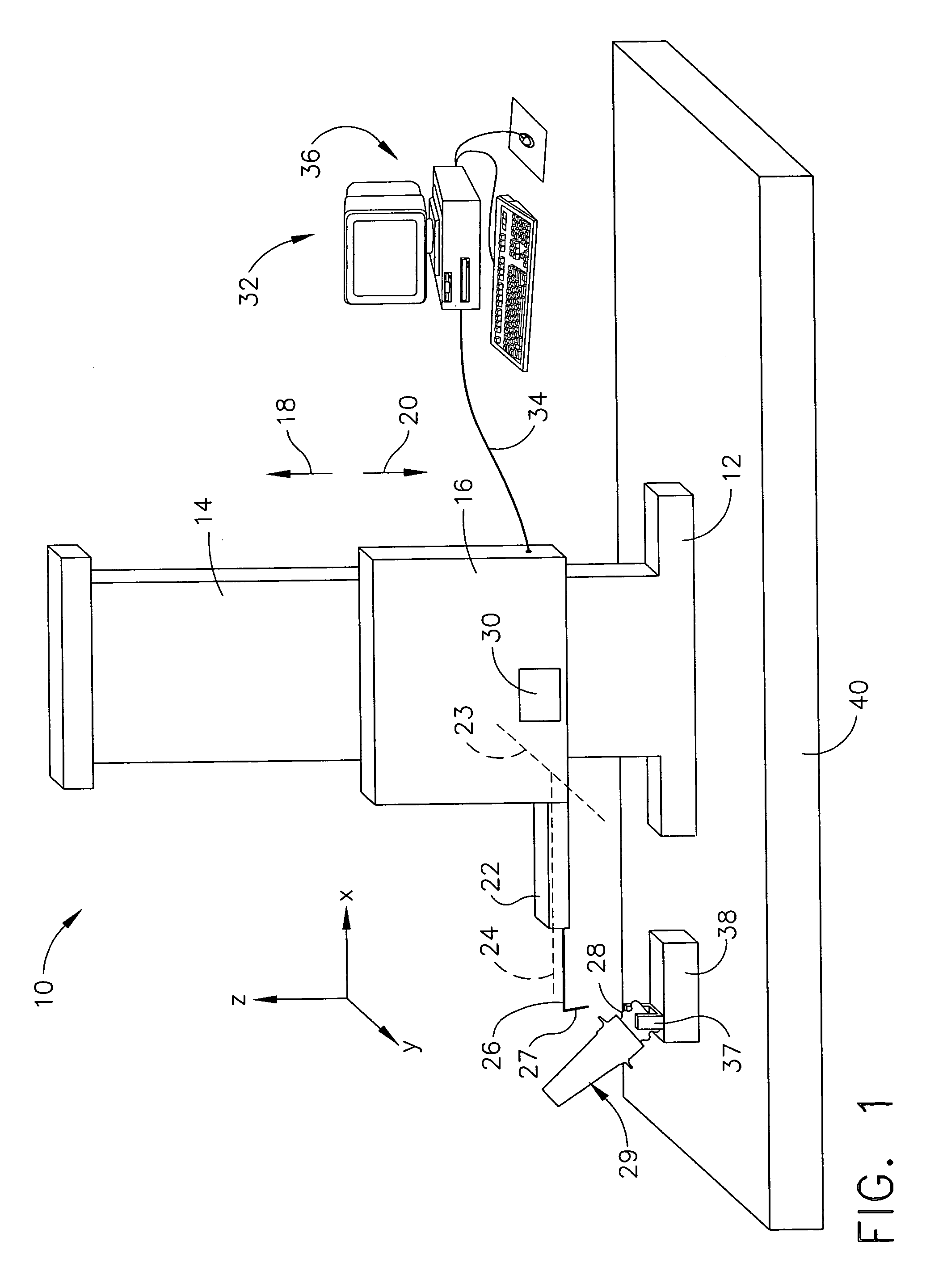
[0011]FIG. 1 is a schematic view of an exemplary embodiment of a profile measuring gauge system 10. System 10 includes a base 12 that supp...


PUM


Abstract

Methods and apparatus for inspecting a component are provided. The method includes receiving a plurality of data points that define a shape of the component, fitting the received data points to a curve that defines a predetermined model shape, and comparing the received data points to the curve defining the predetermined model shape to determine a break radius of the component.

Description

BACKGROUND OF THE INVENTION[0001]This invention relates generally to non-destructive inspection and, more particularly, to dimensional inspection of fabricated components.[0002]Dimensional inspection techniques are used in many applications where the non-destructive evaluation (NDE) of a workpiece or component is desired. At least some known inspection techniques include a visual or manual inspection to facilitate determining a service condition of a component. A knowledgeable and skilled technician may be able to ascertain the worthiness of a particular component for replacement using visual or manual inspection, however visual or manual inspection may not be accurate enough for modem components, nor repeatable for quality verification purposes. For example, a compressor blade dovetail outer edge break radii may be small and span only a few degrees of arc, which may require a relatively accurate relative measurement to determine the actual radius.BRIEF DESCRIPTION OF THE INVENTION[...

Claims


Application Information

Patent Timeline
Patent Type & Authority Patents(United States)
IPC IPC(8): G01B5/20
CPCG01B7/293G01B7/28
Inventor INGRAM, DOUGLAS EDWARDLITTLE, FRANCIS HOWARDWILKINS, MELVIN HOWARD
Owner GENERAL ELECTRIC CO
Features
  • R&D
  • Intellectual Property
  • Life Sciences
  • Materials
  • Tech Scout
  • Unparalleled Data Quality
  • Higher Quality Content
  • 60% Fewer Hallucinations
Learn More