Cover support

a technology for a cover and a support, which is applied in the field of cover support, can solve the problems of cover collapsing, sinking, and boat filling with rainwater

Inactive Publication Date: 2008-03-25
THOMPSON DAVID M
View PDF2 Cites 7 Cited by
  • Summary
  • Abstract
  • Description
  • Claims
  • Application Information

AI Technical Summary

Benefits of technology

[0011]The disc member has four recesses for receiving up to four lines. The lines can be extended from the recesses outward to stabilize the cover support. Each recess has a circular wall extending downward. The circular wall serves to reinforce the disc member. Each recess wall is also juxtaposed adjacent the socket to reinforce the socket. Each recess has a floor and a drain hole. Each recess has an interior cavity to receive a terminal knot in the line so as not to abrade the boat cover.
[0012]A step is placed against the sole, to prevent the strut from slipping transversely. The step has a pocket to receive the strut. The step has grip members extending downward.

Problems solved by technology

Either end of the strut can slip transversely, or sideways, resulting in the cover collapsing.
The boat can then fill with rainwater and sink.

Method used


Image

  • Cover support
  • Cover support
  • Cover support

Examples


Embodiment Construction

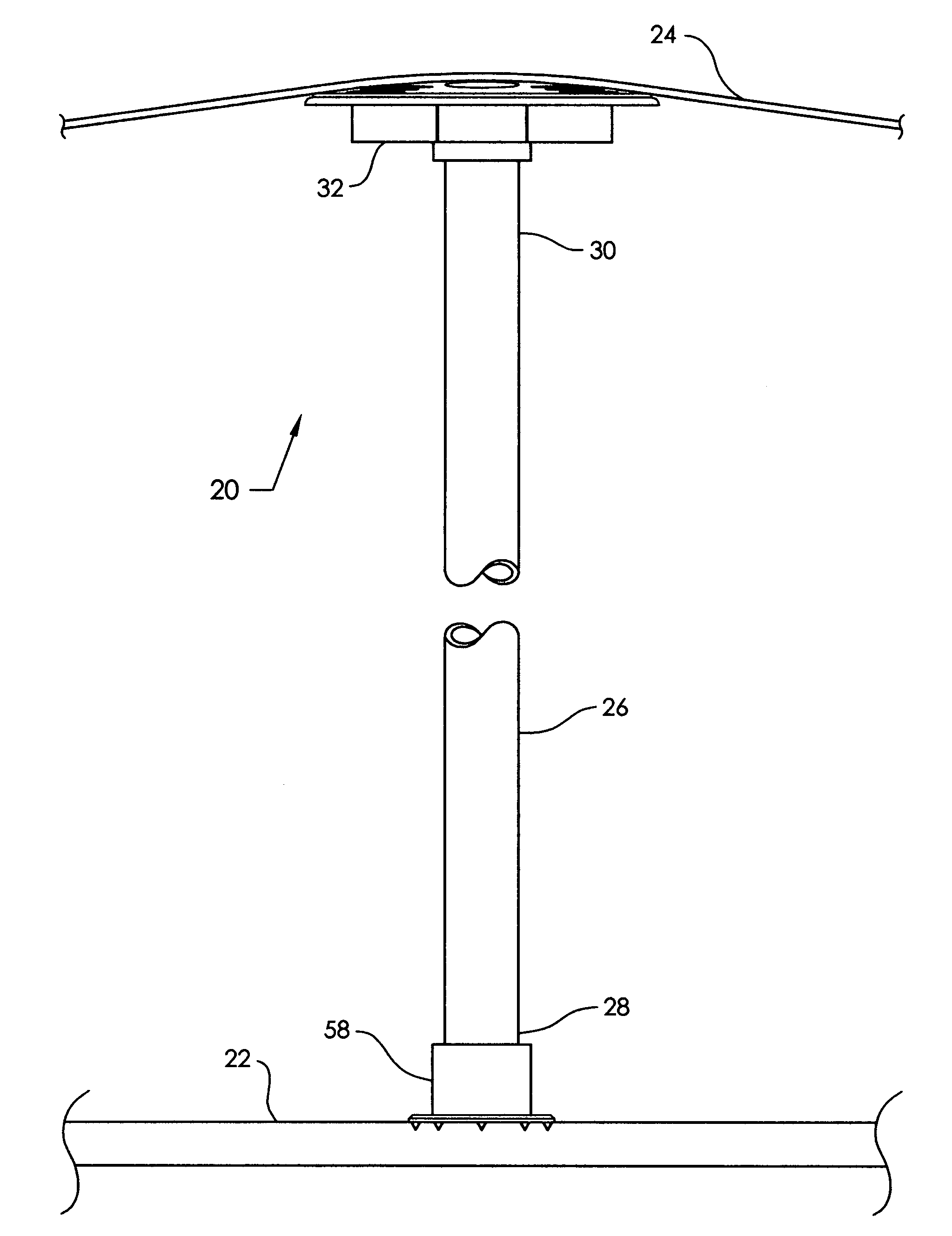
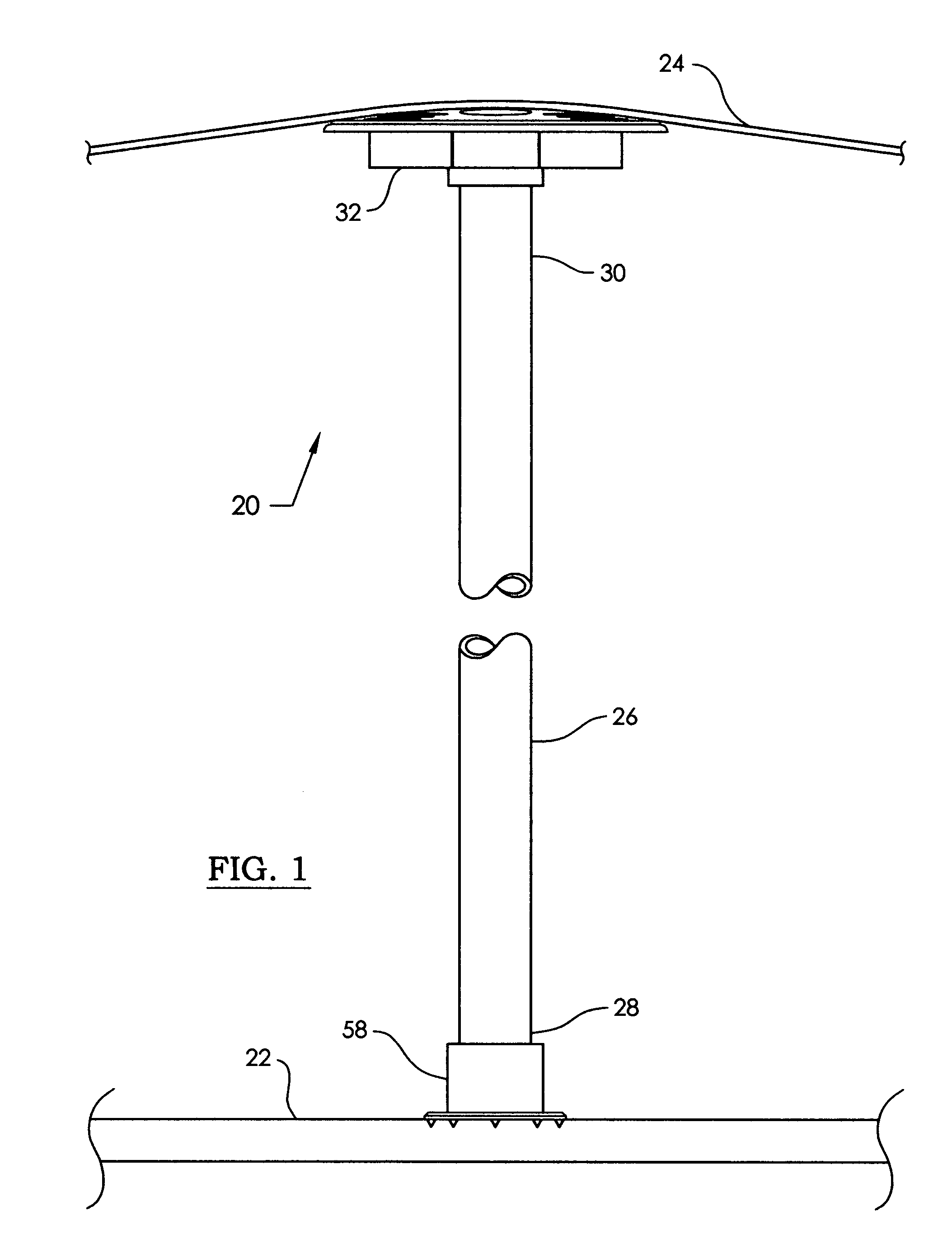
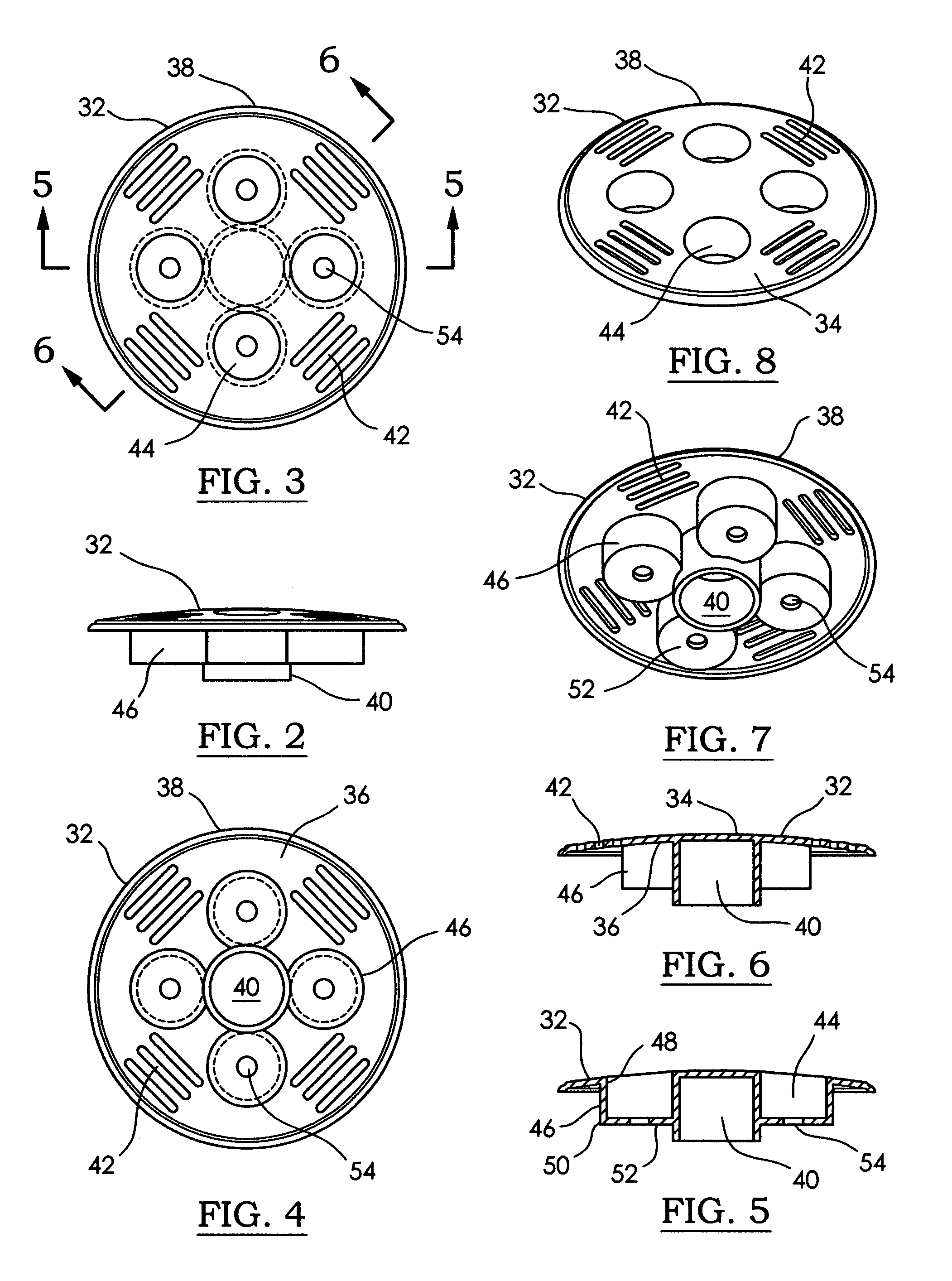
[0047]Referring now to the drawing, and especially to FIGS. 1-15 thereof, a cover support is shown at 20, and is for use in connection with a boat (not shown). The boat has a sole (a floor) 22, and a boat cover 24. A generally vertical strut 26 extends from a lower end 28 adjacent the sole 22 to an upper end 30 adjacent the cover 24. The cover support 20 comprises a disc member 32 having a convex upper surface 34 for placement against the cover 24. The disc member 32 has a lower surface 36, and a periphery 38. The disc member 32 has a socket 40 extending downward from the lower surface 36. The socket 40 is adapted to receive the strut upper end 30.

[0048]The disc member 32 has a plurality of slots 42 spaced apart around the periphery 38. Preferably, the slots 42 are arrayed in four groups of at least two, and preferably three. The slots 42 extend through the disc member 32 from the upper surface 34 to the lower surface 36. The groups are spaced angularly apart around the disc member ...


PUM


Abstract

A boat cover support has a disc member placed against the cover. A vertical strut is received in a socket extending downward from the disc member. The socket has two opposed, semicircular walls to receive a circular strut. The ends of the socket walls are integral with the recesses. The ends of the socket walls are spaced apart to form a transverse notch through the socket to receive a rectangular strut. The disc member has slots arrayed in groups of three around the periphery. Straps extending from the slots outward are attached to the boat structure to stabilize the cover support. The disc member has four recesses with walls extending downward to reinforce the disc member and the socket. Lines extending from the recesses outward are attached to the boat structure to stabilize the cover support. Each recess has an interior cavity to receive a terminal knot in the line so as not to abrade the boat cover. A step is placed against the boat sole, to prevent the strut from slipping transversely.

Description

CROSS-REFERENCE TO RELATED APPLICATIONS[0001]Not ApplicableSTATEMENT REGARDING FEDERALLY SPONSORED RESEARCH OR DEVELOPMENT[0002]Not ApplicableBACKGROUND OF THE INVENTION[0003]This invention relates to the field of tent and boat cover supports, and more particularly to a disc structure to aid in supporting a fabric boat cover or tent.[0004]It is well known that tents and boat covers require a rigid support centrally located and pushing upward to balance the weight of the cover and the downward pull of tent guy lines or boat snap fasteners. The rigid support typically takes the form of a pole or strut, which places great stress on the fabric, which then must be reinforced so as not to tear. Either end of the strut can slip transversely, or sideways, resulting in the cover collapsing. The boat can then fill with rainwater and sink.[0005]Accordingly, there is a need to provide a cover support that can distribute stress over a wide area of the cover, so as to prevent tearing of the cover...

Claims


Application Information

Patent Timeline
IPC IPC(8): B63B17/00
CPCB63B17/02
Inventor THOMPSON, DAVID M.
Owner THOMPSON DAVID M
Why Eureka
Try Eureka