Image processing system for use with a patient positioning device

Active Publication Date: 2008-03-25
VISION RT LTD
View PDF20 Cites 120 Cited by
  • Summary
  • Abstract
  • Description
  • Claims
  • Application Information

AI Technical Summary

Problems solved by technology

A fundamental problem with radiotherapy is the need to position the patient in the same position, when obtaining diagnostic images and each of the subsequent times when radiation is applied to the patient=s body.

Method used


Image

  • Image processing system for use with a patient positioning device
  • Image processing system for use with a patient positioning device
  • Image processing system for use with a patient positioning device

Examples


Embodiment Construction

Patient Positioning System

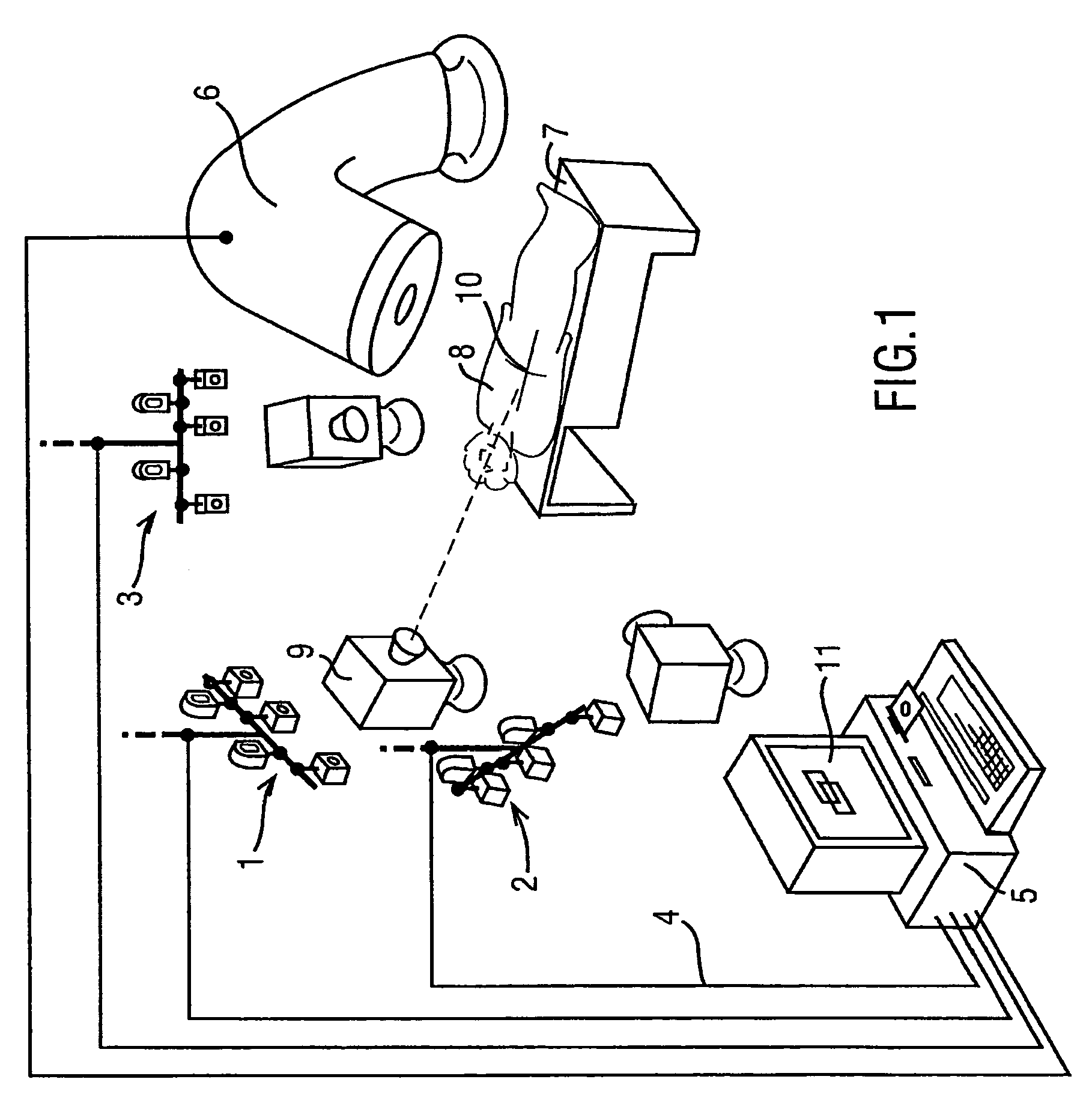
[0026]FIG. 1 is a schematic diagram of a patient positioning system in accordance with an embodiment of the present invention. In accordance with this embodiment, there is provided a set of three camera rigs 1, 2, 3 that are connected by wiring 4 to a computer 5. The computer 5 is also connected to treatment apparatus 6 such as a linear accelerator for applying radiotherapy or an x-ray simulator for planning radiotherapy. A mechanical couch 7 is provided as part of the treatment apparatus 6 upon which a patient 8 lies during treatment. The treatment apparatus 6 and the mechanical couch 7 are arranged such that under the control of the computer 5 the relative positions of the mechanical couch 7 and the treatment apparatus 6 may be varied, laterally, vertically, longitudinally and rotationally. Also provided as part of the system is a laser projection apparatus 9 which is arranged to project three laser beams 10 onto the body of a patient 8 lying on the mecha...


PUM


Abstract

An image processing system (1-5) is provided which obtains images of a patient (8) from multiple view points and which then generates positioning instructions for a mechanical couch (7) to vary the position of a patient. A number of techniques are disclosed in order to calibrate the image processing system so as to enable the image processing system to identify the iso center of radiation beams generated by a treatment apparatus (6). Techniques for processing generated 3 dimensional models to monitor a patient's breathing are also disclosed.

Description

BACKGROUND TO THE INVENTION[0001]1. Field of the Invention[0002]The present invention relates to image processing. More particularly, embodiments of the present invention relate to image processing systems for use with patient positioning devices.[0003]2. Description of the Related Art[0004]One application of the present invention is in the field of radiotherapy. Radiotherapy consists of projecting onto a predetermined region of a patient=s body, a radiation beam so as to destroy or eliminate tumours existing therein. Such treatment is usually carried out periodically and repeatedly. At each medical intervention, the radiation source must be positioned with respect to the patient in order to irradiate the selected region with the highest possible accuracy to avoid radiating adjacent tissue on which radiation beams would be harmful.[0005]A fundamental problem with radiotherapy is the need to position the patient in the same position, when obtaining diagnostic images and each of the s...

Claims


Application Information

Patent Timeline
Patent Type & Authority Patents(United States)
IPC IPC(8): G06T15/00G06T15/06G06T17/20
CPCA61N5/1049G06T7/0018G06T7/002G06T7/0042G06T7/0046G06T7/606G06T15/06G06T17/20A61N5/1069A61N2005/1059G06T2207/10012G06T2207/30004G06T2207/30204G06T2207/30208G06T2207/30244G06T2210/21G06T7/80G06T7/85G06T7/73G06T7/75G06T7/66G06T7/62G06T7/97G06T7/70G03B5/00G03B7/00A61N5/1048
Inventor SMITH, NORMAN RONALDMEIR, IVAN DANIEL
Owner VISION RT LTD
Why Eureka
Try Eureka