Vapor recovery system

a technology of vapor recovery and holding tank, which is applied in the direction of fluid removal, earthwork drilling and mining, and wellbore/well accessories, etc., can solve the problems of too much gas in the holding tank, and no technology on the market to reduce the amount of gas released from the holding tank into the atmospher

Active Publication Date: 2008-04-01
ELECTRONICS DESIGN FOR IND
View PDF6 Cites 29 Cited by
  • Summary
  • Abstract
  • Description
  • Claims
  • Application Information

AI Technical Summary

Problems solved by technology

While it is necessary to have some gas in the holding tank to prevent a fire due to the presence of air, too much gas in the holding tank is a problem due to the potential for the tank to rupture.
However, in recent years concerns over air quality and ozone depletion have pressured the industry to make a change to the method of release.
Other than burning the gas, there is currently no technology on the market for reducing the amount of gas released from the holding tank into the atmosphere.
This is wasteful, because the released gas could be sold to produce useful energy.

Method used


Image

  • Vapor recovery system
  • Vapor recovery system
  • Vapor recovery system

Examples


Embodiment Construction

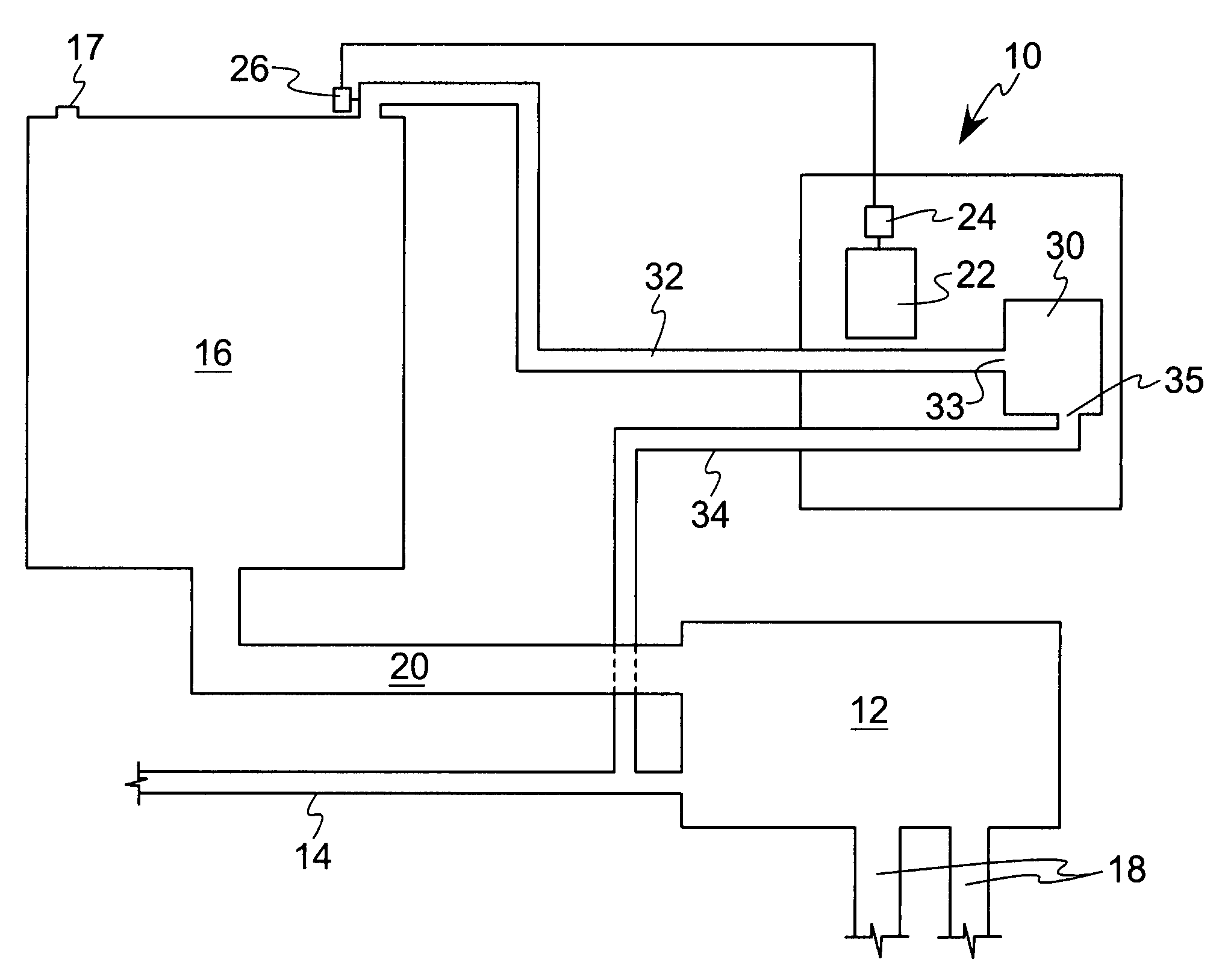
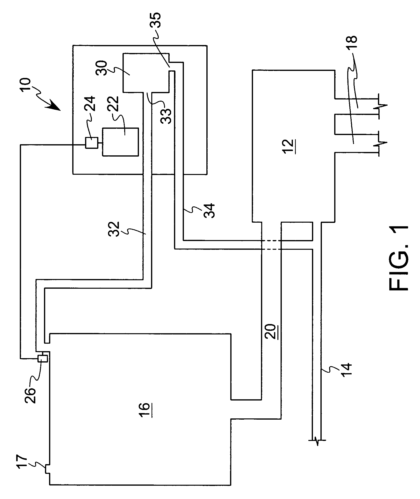
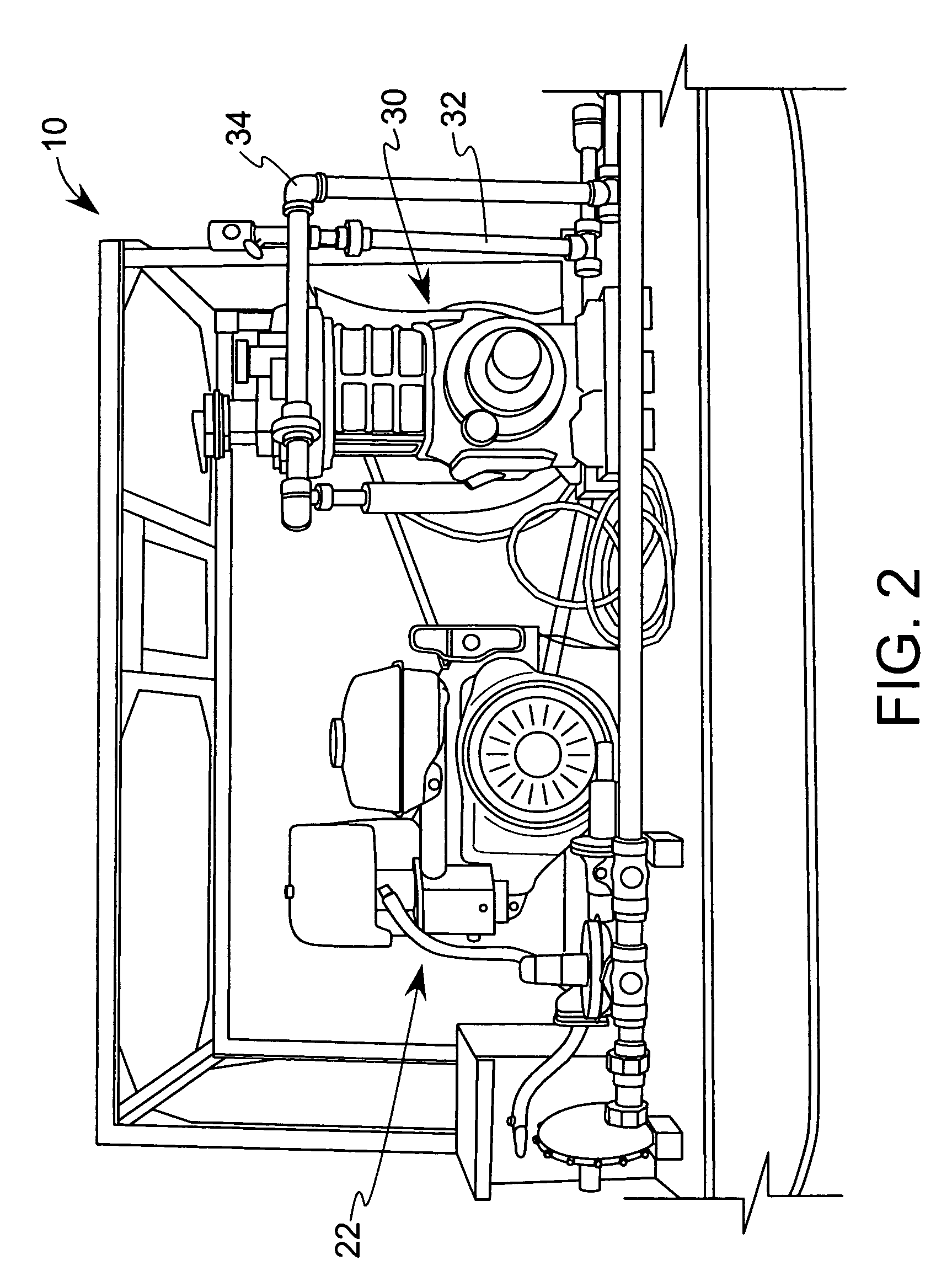
[0014]The invention is a vapor recovery apparatus 10 that is used in combination with conventional oil and gas well production equipment, as illustrated in FIGS. 1 and 2. In such an operation, the oil and gas is drawn from the wells through tubes 18 and pushed into a liquid separator 12. The liquid separator 12 separates the oil from the gas, moving the gas through a sales line 14, which is a pipe connected to natural gas companies' distribution networks. The oil is pushed by the gas through another pipe 20 into the holding tank 16, where it is stored until the holding tank is full and ready to be distributed for sale. Conventional holding tanks 16 have ENARDO brand valve 17 located on the top of the holding tank 16 for releasing gas pressure that builds up in the tank 16. The valve 17 is a safety release valve to protect the holding tank from retaining too much gas pressure inside and thereby causing the holding tank to fracture.

[0015]The vapor recovery apparatus 10, as illustrated...


PUM


Abstract

A vapor recovery apparatus for oil and gas well production that is used in combination with a liquid separator, a sales line and a holding tank includes a compressor, which is drivingly linked to an engine. A first conduit extends from fluid communication with the holding tank to a compressor inlet, while a second conduit extends from a compressor outlet to fluid communication with the sales line. The vapor recovery apparatus also has an electronic controller that is connected to the engine and to a pressure sensor, which is in fluid communication with the gas in the tank.

Description

BACKGROUND OF THE INVENTION[0001]1. Field of the Invention[0002]This invention relates generally to vapor recovery and more specifically, vapor recovery in oil and gas well production equipment.[0003]2. Description of the Related Art[0004]In typical oil and gas well production operations, oil moves from wells through a system of high pressure lines to a holding tank where it is then transferred to a refinery to be used in other applications, for example to power combustion engines. The gas produced in this operation moves through the high-pressure lines, is separated from the oil and then is directed into a sales line where it is distributed to natural gas customers. In separating the oil and gas through this high pressure system, often a small amount of the gas is moved into the holding tank instead of the sales line. Additionally, gas can be produced in the holding tank due to evaporation in the tank. While it is necessary to have some gas in the holding tank to prevent a fire due...

Claims


Application Information

Patent Timeline
Patent Type & Authority Patents(United States)
IPC IPC(8): E21B43/34E21B43/16
CPCE21B43/34
Inventor WYNN, RICHARD L.
Owner ELECTRONICS DESIGN FOR IND
Why Eureka
Try Eureka