Adjustable size shutter with rack and pinion tilt mechanism

a technology of tilt mechanism and adjustable size, which is applied in the direction of building components, constructions, buildings, etc., can solve the problems of prior art devices having manufacturing and operation problems, and the viewing area is reduced through the shutter

Active Publication Date: 2008-04-08
HUNTER DOUGLAS INC +1
View PDF11 Cites 45 Cited by
  • Summary
  • Abstract
  • Description
  • Claims
  • Application Information

AI Technical Summary

Benefits of technology

[0005]One improvement permits easy customization of the height and width of the shutter in an economical, efficient manner.
[0006]Another improvement incorporates an improved mechanism for tilting the louvers of the shutter open or closed without the need for a tilt bar, incorporating the louver mounting pins into the louver drive assembly, enabling the louvers to be readily mounted to or removed from the shutter without any further disassembly required.
[0009]Another improvement allows louvers to be vertically spaced in ⅛ inch increments, which permits customization of the height of the shutter even without the use of light stops along the top and bottom rails.
[0010]Another improvement permits a “clutching” action of the louver drive assembly so that the “timing” of all the louvers may be readily adjusted and synchronized after final assembly.
[0011]Another improvement provides a slide operator, which is surface mounted on a stile, for tilting the louvers open or closed without having to touch any of the louvers and without the need for a tilt bar.

Problems solved by technology

The tilt bar may be considered to detract from the aesthetic appearance of the shutter, and it reduces the viewing area through the shutter.
However, these prior art devices have manufacturing and operational problems.

Method used


Image

  • Adjustable size shutter with rack and pinion tilt mechanism
  • Adjustable size shutter with rack and pinion tilt mechanism
  • Adjustable size shutter with rack and pinion tilt mechanism

Examples


first embodiment

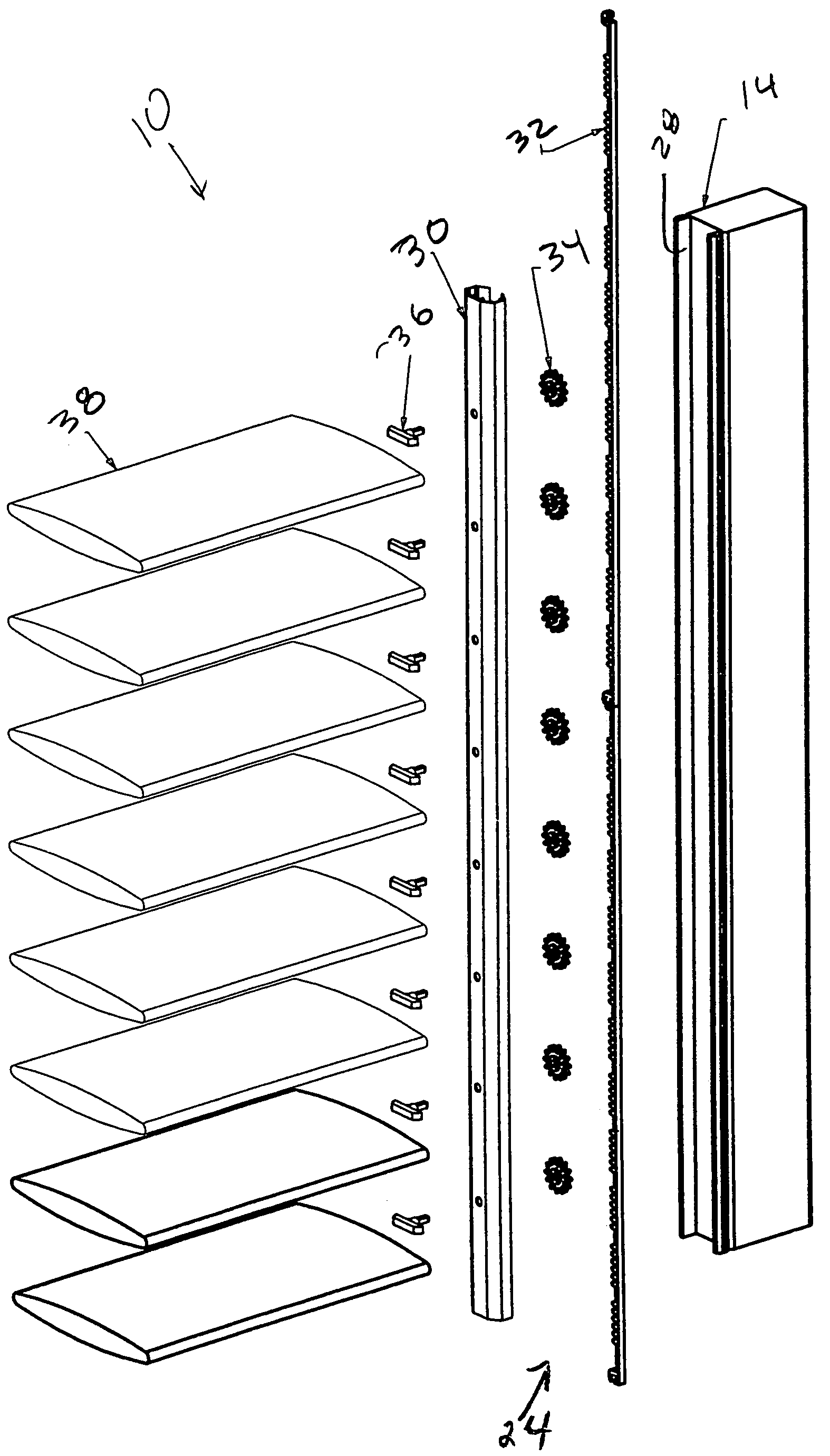
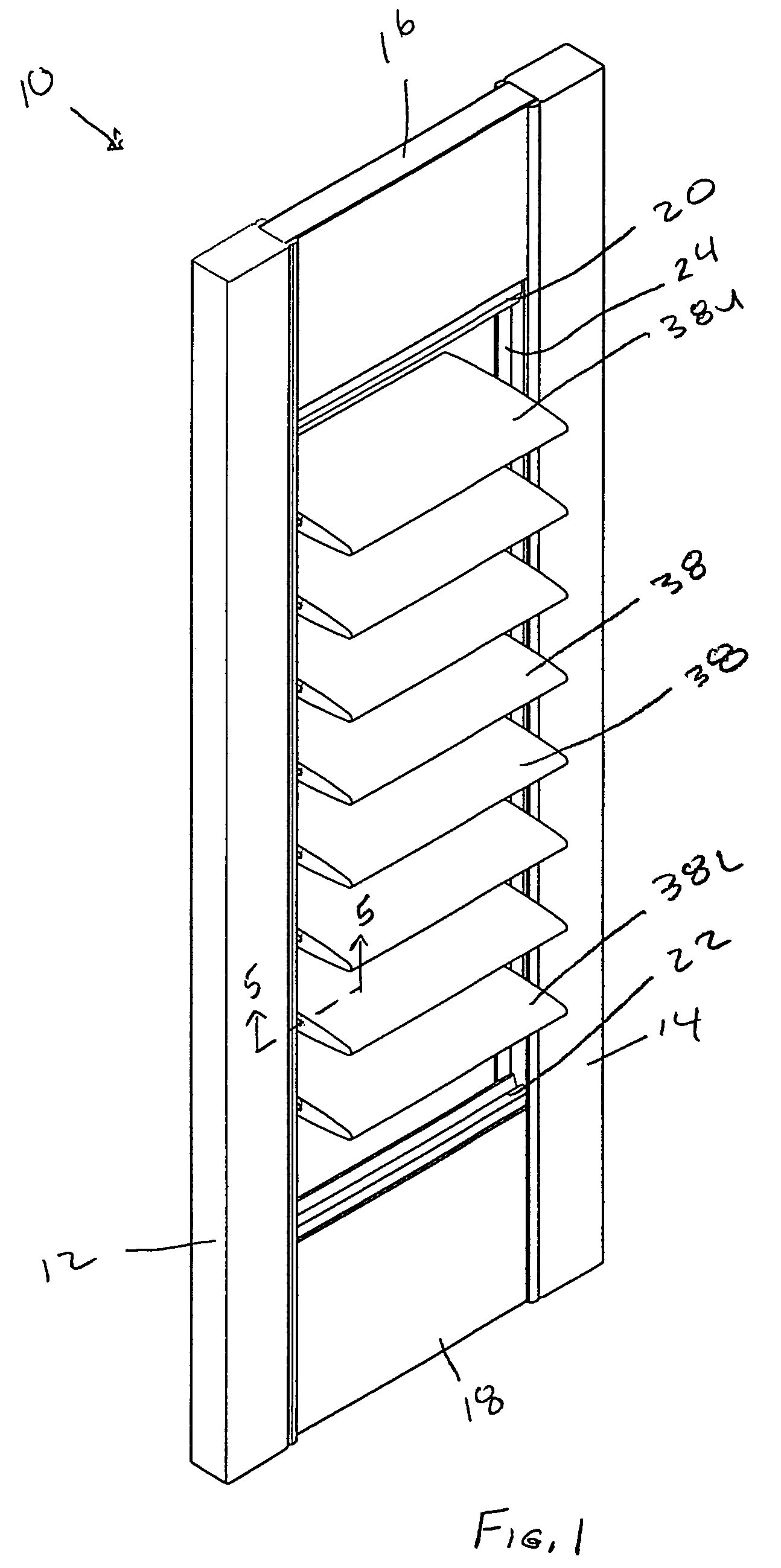
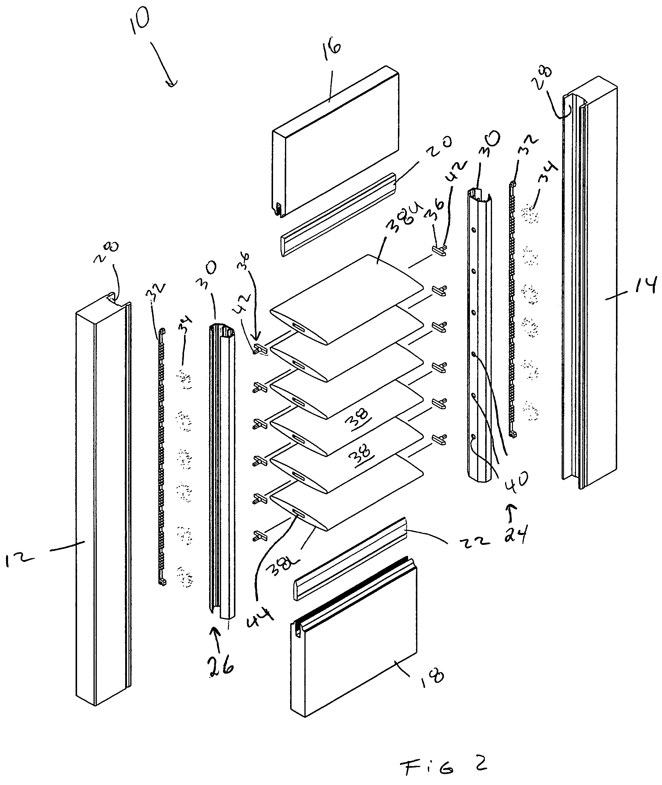
[0049]FIGS. 1 and 2 show a shutter 10 made in accordance with the present invention. The shutter 10 includes left and right vertical stiles 12, 14 and upper and lower horizontal cross rails 16, 18, which are secured together to form a substantially rectangular frame. Upper and lower light stop strips 20, 22 are mounted on the upper and lower cross rails 16, 18. As described in more detail later, identical left and right louver strip assemblies 24, 26 (See also FIGS. 7 and 8) are inserted into U-shaped recesses 28 in the stiles 12, 24 (wherein each louver strip assembly 24, 26 includes a louver strip 30, a rack subassembly 32, a plurality of pinion gears 34, and a plurality of woodruff key mounting pins 36). A plurality of louvers 38 is pivotably mounted to the louver strip assemblies 24, 26. The pivot axes for the louvers 38 are defined by spaced-apart holes 40 in the louver strips 30 and by the pin portions 42 of the woodruff key mounting pins 36, which extend into the holes 40 and...

embodiment 210

[0079]The projections 302 are spaced at approximately 1 inch intervals and allow a “clutching” action useful for “timing” the louvers 38. In this embodiment 210, the alignment position of the pins 136 relative to each other is not as important as it is in the previously described embodiments 10, 110. Once the shutter 210 is assembled, all the louvers 38 may be aligned simply by rotating all the louvers 38 to the fully closed position (whether fully closed room-side up or room-side down). The projections 302 on the smooth back side of the rack 32′ provide some “give” to the rack 32′ so that it flexes enough for the gears 34′ to skip over one or more of the teeth 74′ until all of the louvers 38 are aligned relative to each other.

[0080]Except for the differences discussed above (namely the continuously toothed rack assembly 32′, the self-timing feature of the rack assembly 32′ thanks to the projections 302, and the spur gear 34′ with a diametrical pitch to fit the rack pitch of 0.125 i...


PUM


Abstract

A shutter is provided that utilizes a rack and pinion mechanism for tilting the louvers of the shutter. The rack and pinion mechanism preferably is hidden within the stiles of the shutter. In a preferred embodiment, the louvers of the shutter may be installed and removed without disassembling the assembled frame and rack and pinion mechanism.

Description

[0001]This application claims priority from U.S. Provisional Application Ser. No. 60 / 464,889, filed Apr. 22, 2003, which is hereby incorporated by reference.BACKGROUND OF THE INVENTION[0002]Shutters are designed to cover architectural openings, such windows. Since these openings may come in various sizes, it is desirable to supply shutters which can accommodate varying opening sizes. The present invention addresses the issue of supplying shutters which are readily adjustable to fit into openings of varying height or length. Also, shutters typically include a tilt bar, attached to every louver, for tilting the louvers to an open or closed position. The tilt bar may be considered to detract from the aesthetic appearance of the shutter, and it reduces the viewing area through the shutter. The use of concealed tilt bars and rack and pinion driven louvers is known in the prior art. However, these prior art devices have manufacturing and operational problems.[0003]In typical prior art emb...

Claims


Application Information

Patent Timeline
Patent Type & Authority Patents(United States)
IPC IPC(8): E06B7/086
CPCE06B7/086E06B7/096
Inventor ANDERSON, RICHARD N.FRASER, DONALD E.
Owner HUNTER DOUGLAS INC
Why Eureka
Try Eureka