Conveyor discharge device

a discharge device and conveying device technology, applied in the direction of passenger handling apparatus, chutes, special-purpose vessels, etc., can solve the problems of narrow windrow of material, high cost and time consumption, etc., and achieve the effect of reducing the workload of operators

Inactive Publication Date: 2008-04-08
ROTEC INDS
View PDF9 Cites 8 Cited by
  • Summary
  • Abstract
  • Description
  • Claims
  • Application Information

AI Technical Summary

Benefits of technology

[0008]According to a preferred embodiment of this invention, a system for discharging material from a construction implement relative to a construction surface includes a device that imparts a variable frequency and / or oscillation motion to a conveyor discharge resulting in a pendulum motion of the discharge feed. One resulting benefit of this invention is a substantially larger windrow of material that allows the discharging machine or conveyor to move slowly and methodically, thus reducing operator workload.

Problems solved by technology

This process is costly and time consuming because numerous trucks are required to transport the material to the construction site.
Such conveyors traditionally use a fixed discharge device that results in a very narrow windrow of material.

Method used


Image

  • Conveyor discharge device
  • Conveyor discharge device
  • Conveyor discharge device

Examples


Embodiment Construction

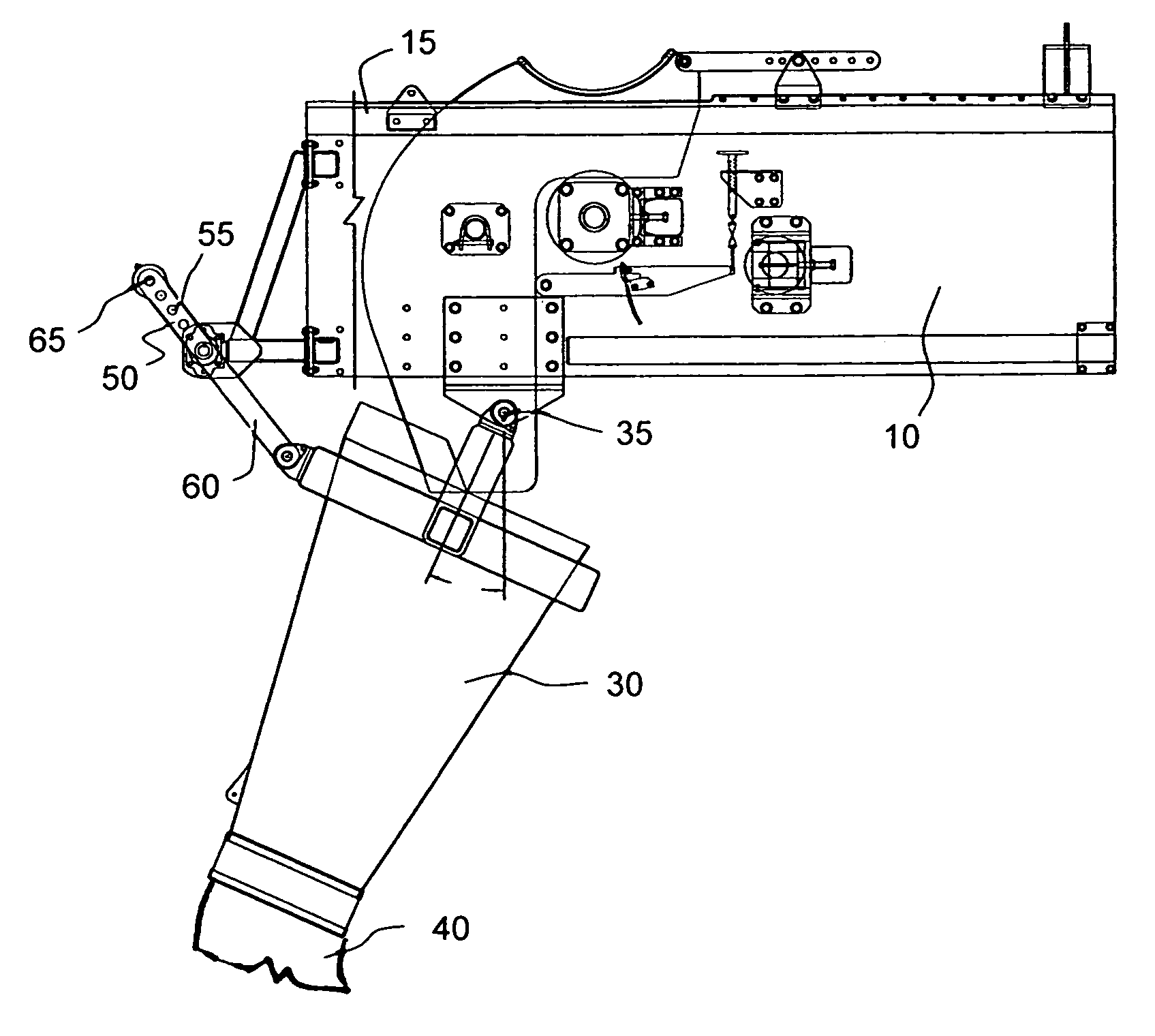
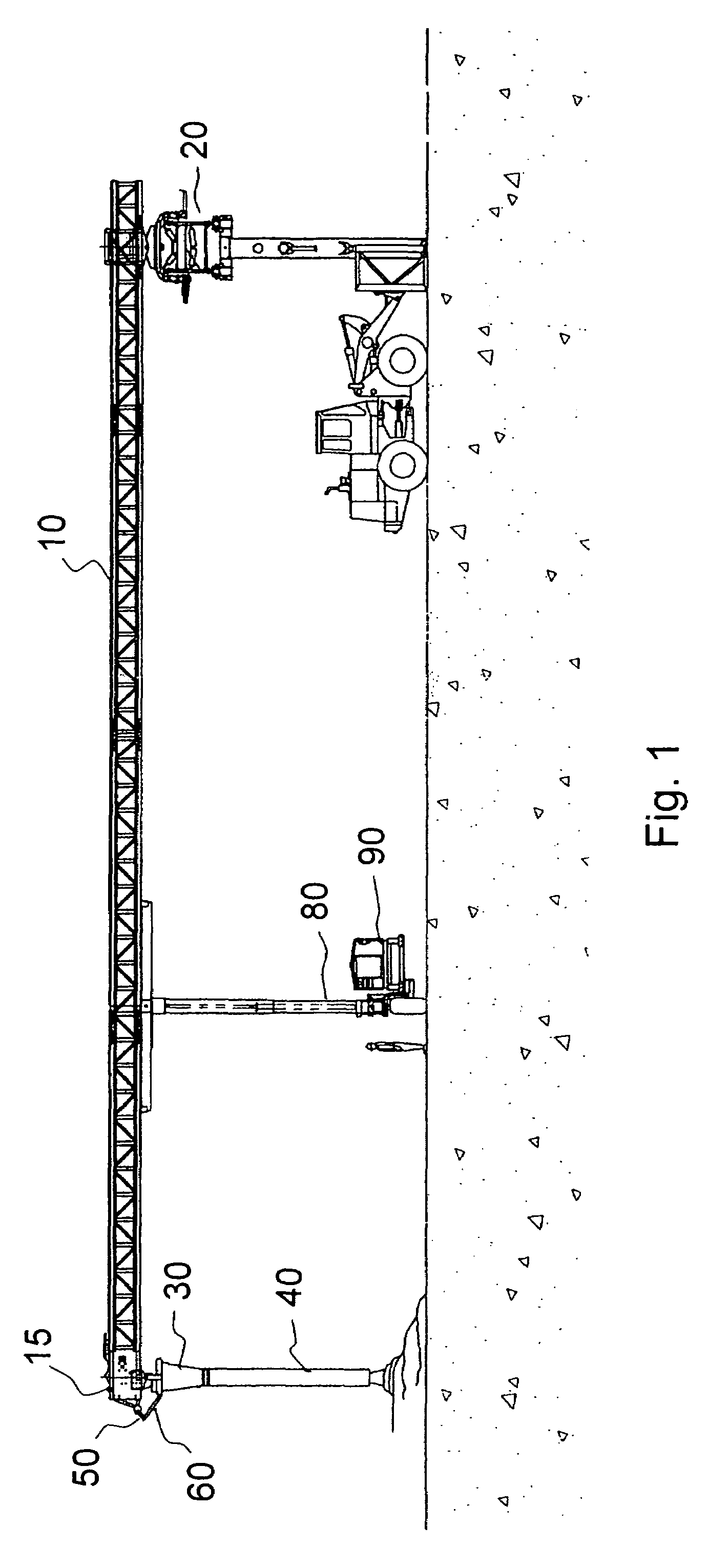
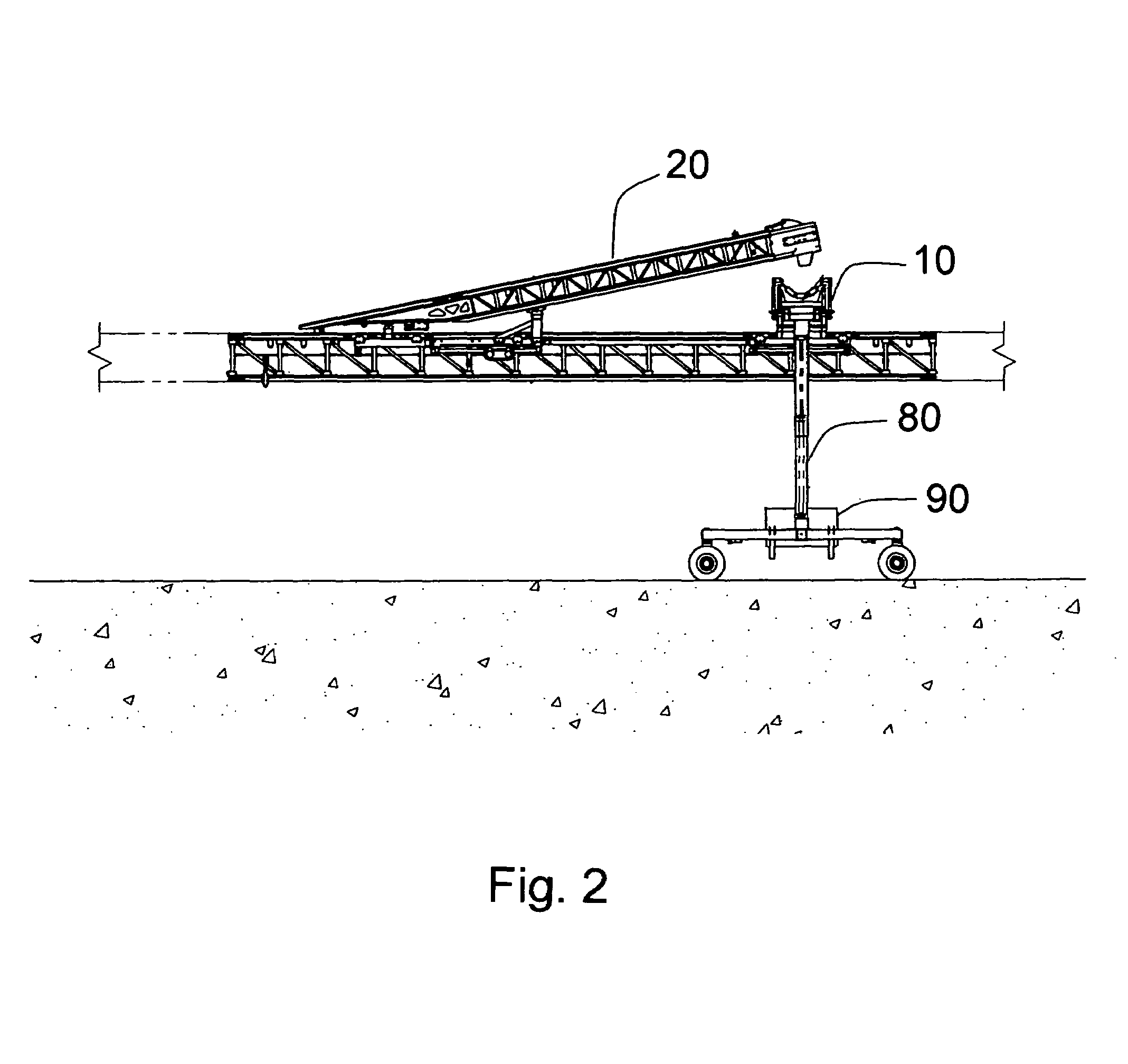
[0019]As briefly described thus far, large scale construction projects such as dams, embankments, landfills, land reclamation, roadways and similar such projects typically require vast amounts of material distribution over very large areas. Examples of such material include roller compacted concrete, conventional concrete, gravel and / or other similar aggregate materials. Conveyors or similar construction implements are typically used to discharge a windrow of material, particularly high-weight, high-volume aggregate materials such as concrete or gravel, in front of other machines that, later on, spread the material over a much larger work area. Until this invention, conveyors have used a fixed discharge device that resulted in a very narrow windrow of material. Use of such a discharge device may result in a narrow windrow that forms discrete piles of material requiring intense spreading activity.

[0020]In a typical application, such as shown in FIGS. 1 and 2, discharge conveyor 10 wi...


PUM


Abstract

A device for spreading aggregate material from a discharge conveyor onto a work surface includes a tremie attached relative to the discharge conveyor and a flexible hose connected to the tremie. A crank connected between the tremie and the discharge conveyor permits adjustment of a frequency and an amplitude of the tremie to provide a desired windrow of material on the surface. A distal end of the discharge conveyor is preferably moveable relative to a supply of material to further optimize the desired windrow of material.

Description

[0001]This application claims priority to U.S. provisional application 60 / 658,637 filed 3 Mar. 2005.BACKGROUND OF THE INVENTION[0002]1. Field of the Invention[0003]This invention relates to a system and method for discharging material relative to a construction surface.[0004]2. Description of Related Art[0005]Dams, roads and similar large scale construction projects that require building up a surface in layers. Concrete and rock filled dams, large concrete pads and roads are traditionally constructed by hauling rocks and / or concrete from a blasting site, concrete plant or quarry to the construction site using large dump trucks and / or mixing trucks. In rock-filled dams, a bulldozer then spreads the rocks and rollers are used to compact the material until it reaches a specified density. Similarly, in concrete construction, a cantilevered trough pours the concrete until it reaches a desired level.[0006]Bulldozers and trucks also typically prepare roads on the dam so that trucks can dri...

Claims


Application Information

Patent Timeline
Patent Type & Authority Patents(United States)
IPC IPC(8): B65G17/36
CPCB65G65/28B65G69/0441B65G69/10E04G21/04E04G21/0409
Inventor OURY, ROBERTARNDT, BRUCE
Owner ROTEC INDS
Why Eureka
Try Eureka