Fluid supply assembly

a technology of supply assembly and fluid, which is applied in the direction of liquid handling, caps, separation processes, etc., can solve the problems of unnecessarily complicated paint cups and users cannot use all of the fluid, and achieve the effect of improving the seal

Inactive Publication Date: 2008-04-08
CARLISLE FLUID TECH INC +1
View PDF227 Cites 40 Cited by
  • Summary
  • Abstract
  • Description
  • Claims
  • Application Information

AI Technical Summary

Benefits of technology

[0005]Therefore, there remains a need for a fluid supply assembly which provides an improved seal to prevent fluid leakage.

Problems solved by technology

In addition, the user cannot use all of the fluid because it moves around in the fluid supply cup and air can be drawn into the drain hole.
Moreover, the paint cup is unnecessarily complicated.

Method used


Image

  • Fluid supply assembly
  • Fluid supply assembly
  • Fluid supply assembly

Examples


Embodiment Construction

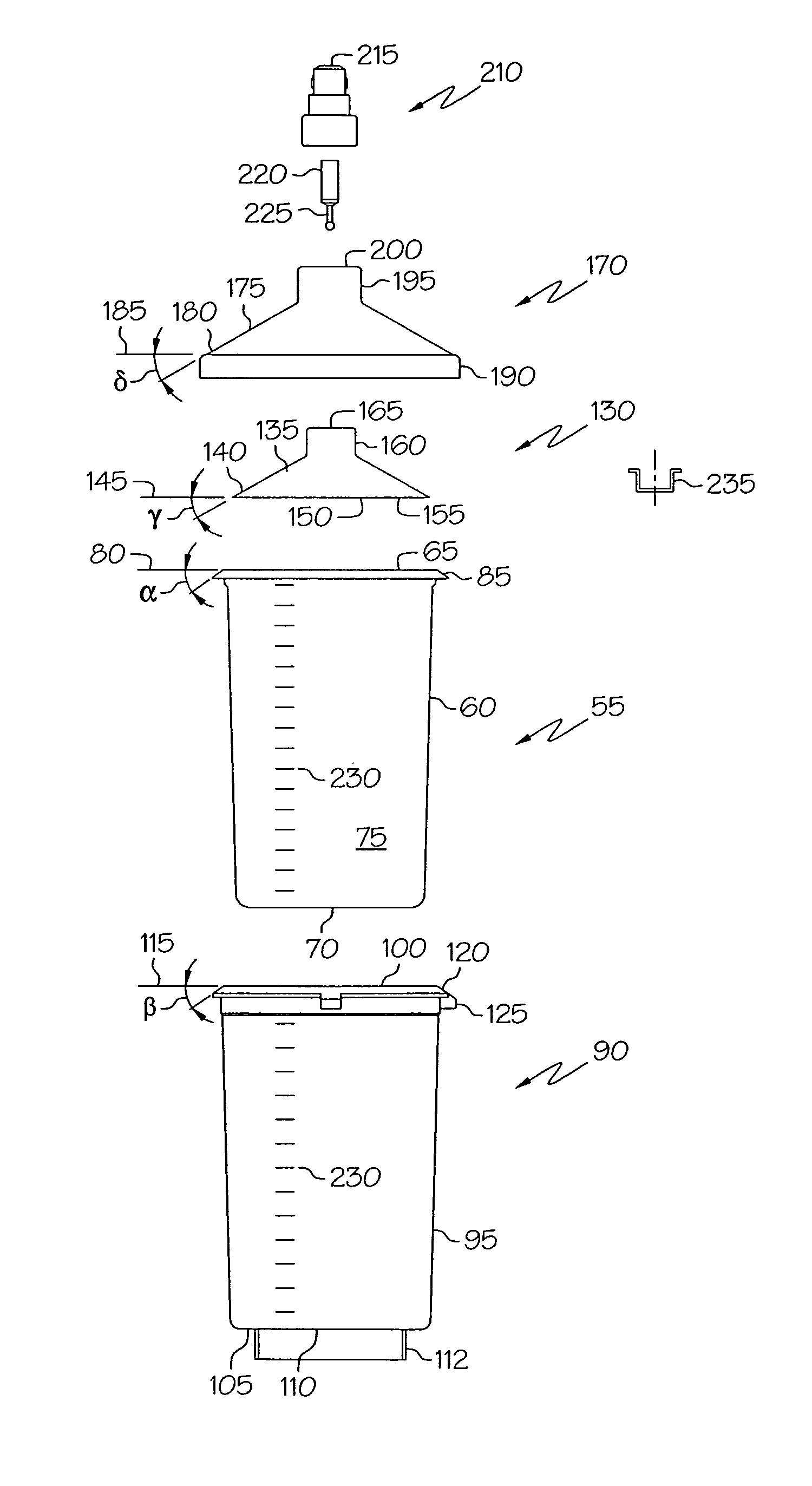
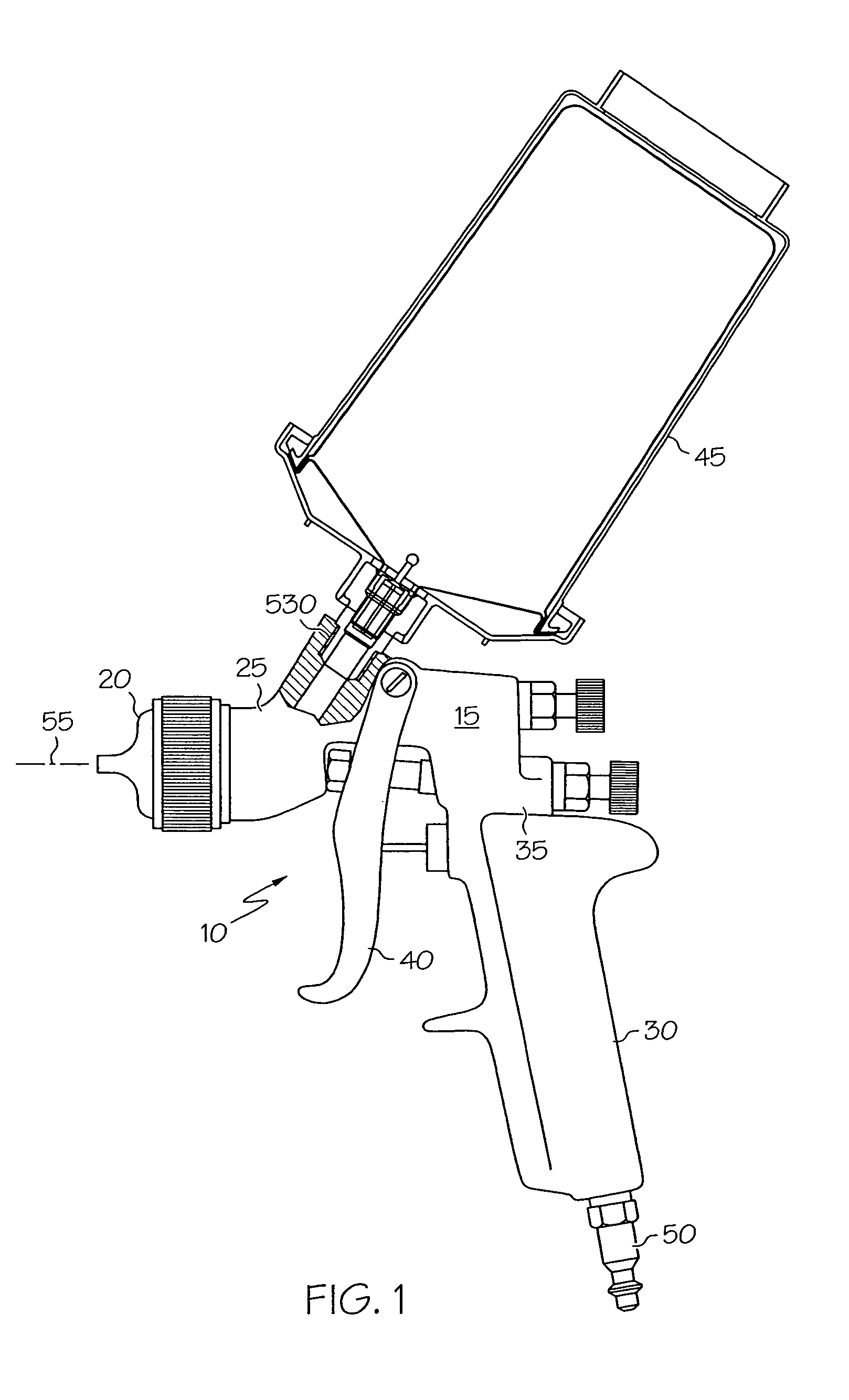
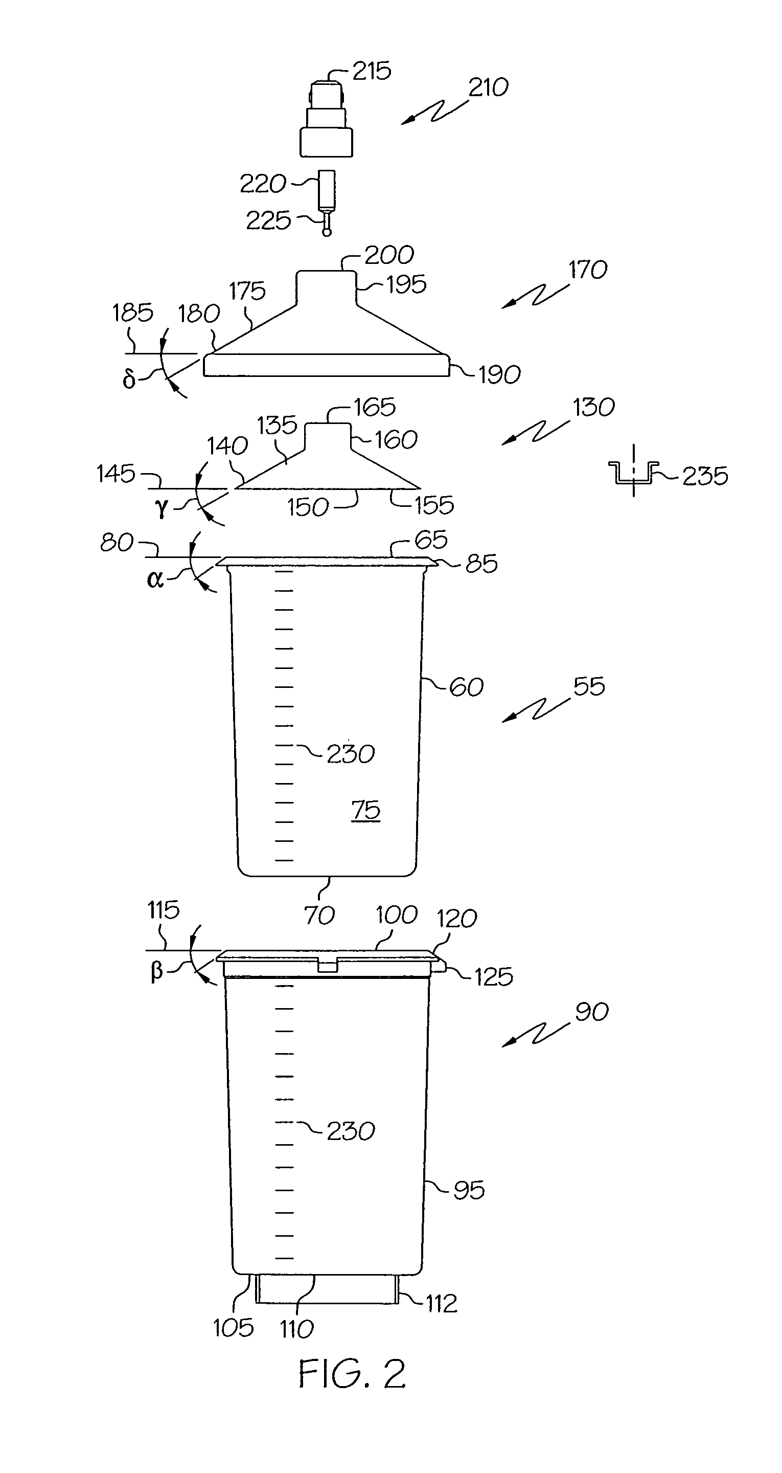
[0027]A fluid supply assembly attached to a fluid applicator is shown in FIG. 1. In one embodiment, the fluid supply assembly is for feeding liquid, such as paint, to the fluid applicator, such as a paint sprayer. The present invention will be described for a paint sprayer, such as a gravity feed paint sprayer for use in applying paint to coat substrate surfaces. The paint sprayer can be used in the automotive refinishing market, such as automobile body shops, for repainting automobiles. Although the fluid supply assembly is described for a paint sprayer, it is not limited to such use. It can be used for supplying other flowable liquids, including, but not limited to, beverages, foods, condiments (such as ketchup), gasoline, petrochemicals and hydrocarbons, water, water-based solutions, solvent-based solutions, emulsions, adhesives, and the like.

[0028]Referring to FIG. 1, a paint sprayer 10 is shown. It includes a body 15, a nozzle assembly 20 secured to a front end 25 of body 15, a...


PUM

PropertyMeasurementUnit
angleaaaaaaaaaa
angleaaaaaaaaaa
angleaaaaaaaaaa

Abstract

A fluid supply assembly. The fluid supply assembly includes a disposable cup and lid, and a reusable cup holder and outer lid. A method of preparing a fluid supply assembly for use with a fluid supply applicator is also described.

Description

BACKGROUND OF THE INVENTION[0001]The present invention is directed generally to a fluid supply assembly for a fluid applicator, and more particularly to a fluid supply assembly having an improved seal between a disposable cup and a disposable lid.[0002]Some fluid applicators, such as gravity feed paint spray guns, have a fluid supply cup mounted on top of the fluid applicator. The fluid supply cup is typically reusable. Fluid, such as paint, is generally measured and mixed in a separate container, and then poured into the fluid supply cup for use. The container for measuring and mixing must be either cleaned or disposed of. During fluid application, the user must be careful not to tip the fluid applicator too much, or fluid will leak out a vent in the fluid supply cup. In addition, the user cannot use all of the fluid because it moves around in the fluid supply cup and air can be drawn into the drain hole.[0003]Attempts have been made to provide fluid supply assemblies which do not ...

Claims


Application Information

Patent Timeline
Patent Type & Authority Patents(United States)
IPC IPC(8): B65D21/02B05B7/24
CPCB05B7/2408B05B7/2478Y10T29/49826B05B7/24
Inventor KOSMYNA, MICHAEL J.
Owner CARLISLE FLUID TECH INC
Why Eureka
Try Eureka