Polarization and frequency diverse radar system for complete polarimetric characterization of scatterers with increased scanning speed

a radar system and scanning speed technology, applied in the field of radar systems, can solve the problems of meteorological significance of certain parameters in the scattering matrix that cannot be obtained with this technique, and the measurement of the error rate of the doppler velocity, so as to achieve the effect of maximization isolation

Inactive Publication Date: 2008-04-08
ADVANCED RADAR CORP
View PDF5 Cites 26 Cited by
  • Summary
  • Abstract
  • Description
  • Claims
  • Application Information

AI Technical Summary

Benefits of technology

[0019]In accordance with the invention there is provided a method and apparatus, whereby a scanning, polarization and frequency diverse radar system measures the complete polarimetric characterization of weather targets without loss of scanning speed and without an additional ambiguity in the Doppler velocity beyond that given by Nyquist's sampling theorem. In one embodiment, a linear combination of a horizontally and a vertically polarized signal are transmitted at a predetermined first frequency. Cotemporaneously or nearly cotemporaneously with the transmitted signal of the first frequency, a horizontally polarized signal is transmitted at a predetermined second frequency. Horizontal and vertical receive channels receive echoes at the predetermined first frequency to determine, but not limited to determine, the co-polar elements of the scattering matrix. Horizontal and vertical receive channels receive echoes at the predetermined second frequency to determine, but not limited to determine, the cross-polar elements of the polarization matrix. The predetermined first and second frequencies are selected to maximize isolation yet allow practical implementation.

Problems solved by technology

However, in some cases this assumption is incorrect causing an erroneous Doppler velocity measurement.
However, certain of the parameters in the scattering matrix that cannot be obtained with this technique are meteorologically significant.

Method used


Image

  • Polarization and frequency diverse radar system for complete polarimetric characterization of scatterers with increased scanning speed
  • Polarization and frequency diverse radar system for complete polarimetric characterization of scatterers with increased scanning speed
  • Polarization and frequency diverse radar system for complete polarimetric characterization of scatterers with increased scanning speed

Examples


Embodiment Construction

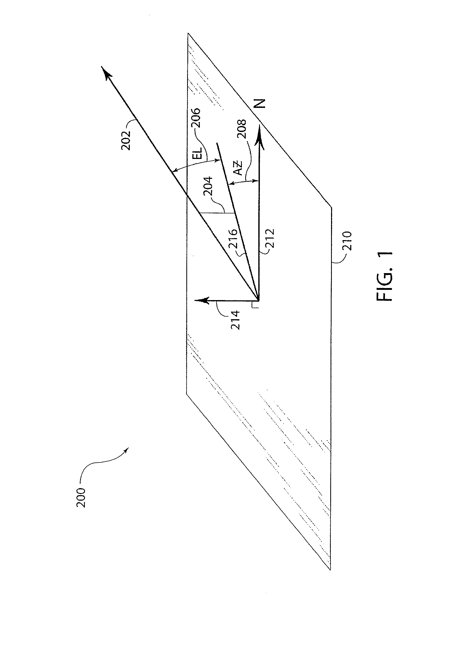
[0025]For purposes of discussion, ground based radars will be assumed in which a gimbaled mount is used to scan a pencil beam antenna 32 in azimuth and elevation as per the general coordinate system 200 shown in FIG. 1. The reference plane 210 is assumed substantially parallel to the local surface of the Earth. The elevation angle 206 defines the pointing direction 202 of antenna 32. Zenith vector 214 is perpendicular to reference plane 210. The projection 216 of pointing direction 202 lying on plane 210 defines the azimuth angle 208 to a northern reference vector 212. An elevation angle of zero degrees is defined to point at the horizon (points lying in plane 210), and an elevation angle of 90 degrees is defined to point to the zenith 214. Azimuth angles 208 are defined about the zenith 214. The zero azimuth reference point is generally aligned to north 212. However, this is only by convention and does not affect the geometry. Radars employing ground-based scanners are introduced h...


PUM


Abstract

A method and apparatus is provided, whereby a scanning, polarization and frequency diverse radar system measures the complete polarimetric characterization of weather targets without loss of scanning speed and without an additional ambiguity in the Doppler velocity beyond that given by Nyquist's sampling theorem. In one embodiment, a linear combination of a horizontally and a vertically polarized signal are transmitted at a predetermined first frequency. Cotemporaneously or nearly cotemporaneously with the transmitted signal of the first frequency, a horizontally polarized signal is transmitted at a predetermined second frequency. Horizontal and vertical receive channels receive echoes at the predetermined first frequency to determine, but not limited to determine, the co-polar elements of the scattering matrix. Horizontal and vertical receive channels receive echoes at the predetermined second frequency to determine, but not limited to determine, the cross-polar elements of the polarization matrix. The predetermined first and second frequencies are selected to maximize isolation yet allow practical implementation.

Description

CROSS-REFERENCES TO RELATED APPLICATIONS[0001]This patent application claims the benefit of U.S. Provisional Applications No. 60 / 236,638, filed on Sep. 29, 2000, and No. 60 / 259,681, filed on Jan. 4, 2001, each of which is incorporated herein by reference.TECHNICAL FIELD[0002]This invention relates to radar systems that transmit and / or receive multiply polarized beams of high frequency energy in a scanning mode to identify the presence, locus and characteristics of scatters in a region of space.BACKGROUND OF THE INVENTION[0003]The first radars for weather detection employed a single, fixed polarization transmission signal and receivers that were optimized to receive that particular polarization.[0004]These first radars usually employed substantially linear polarization. Horizontal or Vertical polarization was most commonly used. It was less common to find single polarization scanning radars for weather detection that employ circular polarization or linear polarization at other than H...

Claims


Application Information

Patent Timeline
Patent Type & Authority Patents(United States)
IPC IPC(8): G01S13/95
CPCG01S7/024G01S13/426G01S13/951G01S7/025Y02A90/10
Inventor RANDALL, MITCH
Owner ADVANCED RADAR CORP
Why Eureka
Try Eureka