
Steering system for off-road vehicle

Inactive Publication Date: 2008-04-15
YAMAHA MOTOR CO LTD
View PDF147 Cites 45 Cited by
  • Summary
  • Abstract
  • Description
  • Claims
  • Application Information

AI Technical Summary

Benefits of technology

[0010]In arrangements featuring an off-center steering shaft (e.g., steering wheel positioned forward of one of a pair of side-by-side seating positions), the tie rod on this side is shorter than the tie rod would be if the steering shaft were centrally positioned on the vehicle in a lateral direction. To compensate for the shortened tie rod, the tie rod on the other side also is shortened to maintain a symmetrical construction. As a result of the shortened tie rods, the imaginary spherical surfaces defined on both sides of the vehicle have a smaller circumference than those that would be defined when the steering system is centrally disposed. With the smaller circumference, the curve defined by the suspension linkage can easy become misaligned with the imaginary spherical surface, which results in greater occurrences of bump steering.
[0011]The wheel suspension can be specially designed to reduce bump steering and to decrease the amount of toe angle change during suspension travel. Such specially suspension designs, however, are limited and cause severe constraints in suspension and steering design.
[0012]A need, therefore, exists for an improved steering system for an off-road vehicle that can reduce bump steering without significantly limiting the design choices of such systems.

Problems solved by technology

The knuckle arm, however, generally is only capable of generally vertical movement along a curve that is regulated by the geometry of the suspension linkage.
This undesirable steering generally is caused by bumps in the road and an interaction of improper lengths and / or angles in the suspension and steering linkages.
During bump steering, the toe angle of the wheel also varies, typically in an undesirable manner.
With the smaller circumference, the curve defined by the suspension linkage can easy become misaligned with the imaginary spherical surface, which results in greater occurrences of bump steering.

Method used


Image

  • Steering system for off-road vehicle
  • Steering system for off-road vehicle
  • Steering system for off-road vehicle

Examples


Embodiment Construction

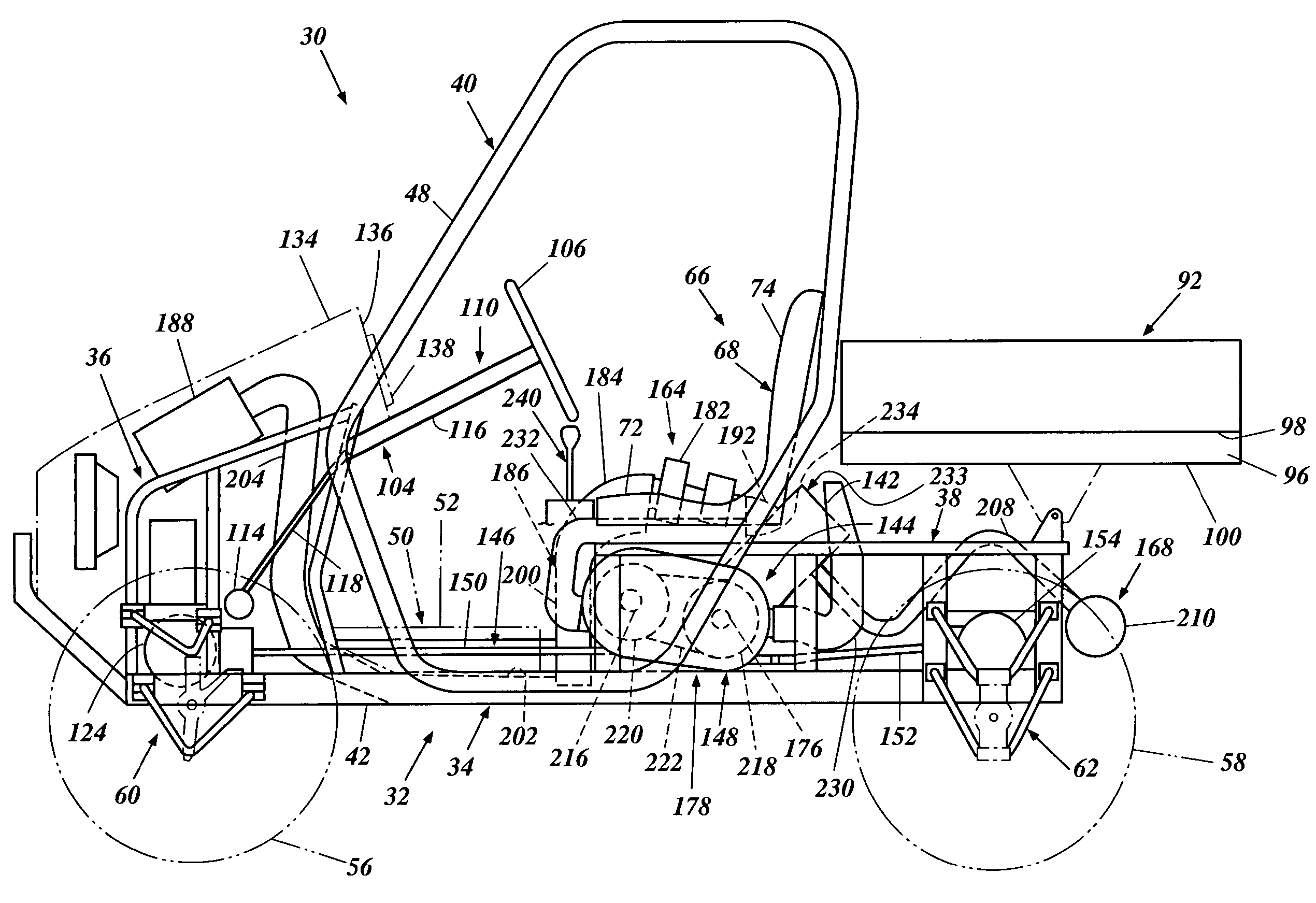
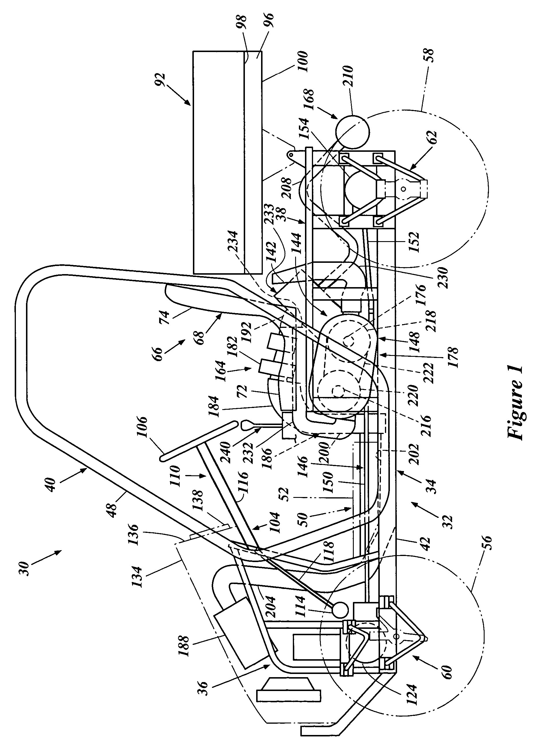
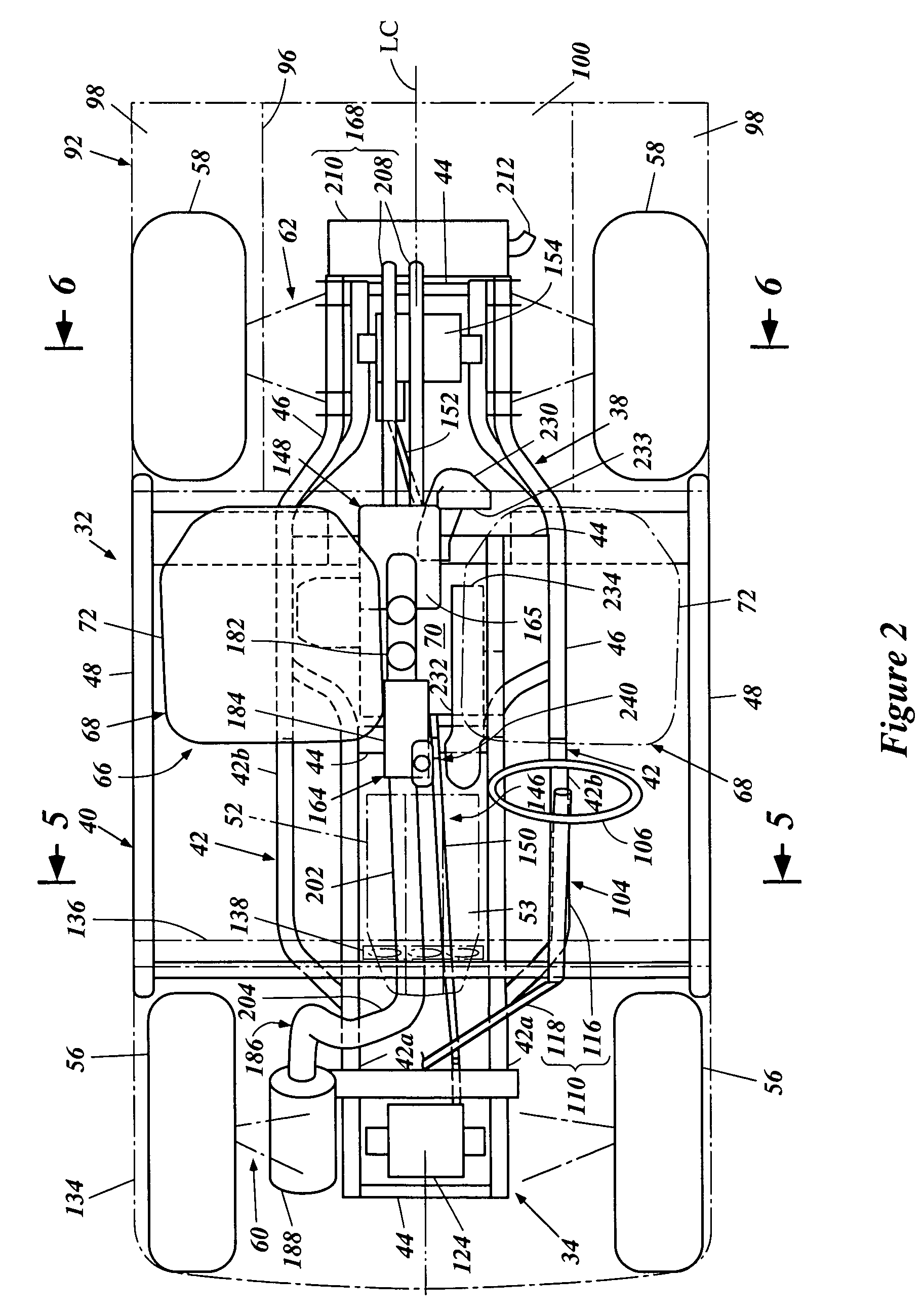
[0024]With reference to FIGS. 1-7, an off-road vehicle is described. While the embodiment of the present invention is described in connection with this particular type of vehicle, those of skill in the art will appreciate that certain features, aspects, and advantages of the present invention may have utility in a wide range of applications for other vehicles. For instance, certain features, aspects and advantages of the present invention can be used with snow vehicles, tractors, utility vehicles, and the like.

[0025]With reference to FIGS. 1, 2 and 5, the off-road vehicle 30 preferably has an open tubular-type frame 32. The illustrated frame 32 comprises a main frame section 34, a front frame section 36, a rear frame section 38 and a compartment frame section (or pillar frame section) 40.

[0026]The main frame section 34 includes a pair of side frame units 42 spaced apart side by side with each other. Each side frame unit 42 comprises a front tubular member 42a and a rear tubular memb...


PUM


Abstract

An off-road vehicle includes a frame and wheels. An engine powers the wheels through a drive system that includes a front differential gear unit. A housing encloses the front differential gear unit. The housing is positioned generally on a longitudinal center plane of the frame with the plane extending generally vertically and fore to aft. A steering system controls directional movement of the front wheels. The steering system includes a steering wheel that is offset relative to the center plane. A steering shaft is connected to the steering wheel and is disposed on the frame for rotation. A pair of tie-rods are coupled with the respective front wheels. A coupling mechanism couples the steering shaft to the tie-rods. The coupling mechanism converts the rotary movement of the steering shaft to an axial movement of each tie-rod. The coupling mechanism includes a rack-and-pinion assembly. A gear case encloses the rack-and-pinion assembly. The gear case is coupled with the differential housing and positioned such that the center plane intersects the gear case.

Description

PRIORITY INFORMATION[0001]The present application is based on and claims the benefit of U.S. Provisional Application No. 60 / 459,947, filed on Apr. 2, 2003, under 35 U.S.C. § 119.BACKGROUND OF THE INVENTION[0002]1. Field of the Invention[0003]The present invention generally relates to a steering system for an off-road vehicle, and more particularly to an improved steering arrangement for an off-road vehicle.[0004]2. Description of Related Art[0005]Off-road vehicles are designed to be operated over rugged terrain. These vehicles are often operated off-road over terrain such as, for example, steep inclines and declines, rough roads, and areas covered in mud and water.[0006]Off-road vehicles typically include a frame that is supported by wheels. In one common arrangement, the vehicle has four wheels, i.e., a pair of front wheels and a pair of rear wheels. A prime mover, such as an internal combustion engine, for instance, is employed to power at least the rear or front wheels, and most ...

Claims


Application Information

Patent Timeline
IPC IPC(8): B60K17/30B62D3/12
CPCB62D3/12
Inventor INUI, AKIRA
Owner YAMAHA MOTOR CO LTD
Learn More