Developing unit and image forming apparatus
a technology of developing unit and image forming apparatus, which is applied in the direction of electrographic process apparatus, instruments, optics, etc., can solve the problems of uneven concentration in vertical obi shape, and achieve the effect of stable thickness, high quantity and uniform concentration
- Summary
- Abstract
- Description
- Claims
- Application Information
AI Technical Summary
Benefits of technology
Problems solved by technology
Method used
Image

Examples
embodiment 1
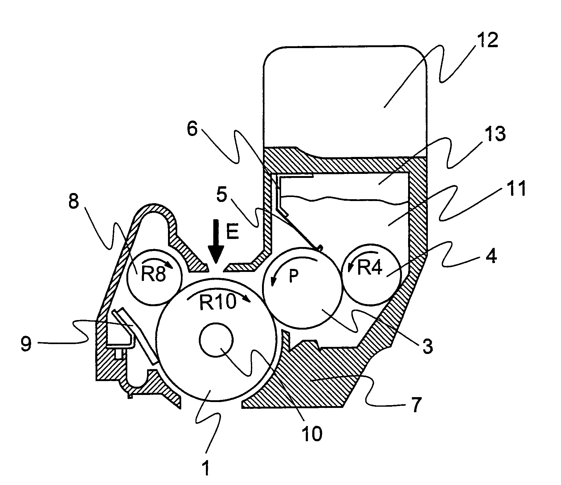
[0060]FIG. 1 is a cross section showing a structure of a developing unit of the present invention.
[0061]In the embodiment 1, a developing unit of the present invention includes a photosensitive drum 1 as an image carrying body, a developing roller 3 as developing member, a providing roller 4, a developing blade 5 as developer layer forming member, a blade holder 6, a frame 7, a charging roller 8, a cleaning blade 9, a fixed shaft 10, toner 11 as developer, a toner cartridge 12 as a developer accommodating section, and a toner tank 13.
[0062]The photosensitive drum 1 is constructed by a basic layer with electroconductivity made from Aluminum and the like and by a surface layer made from organic photosensitive member. The photosensitive drum us fixed onto both sides of the frame 7 as being rotatable around the fixed shaft 10 as a center axis along an arrow direction R10. The photosensitive drum 1 serves as an image carrying body to carry an electrostatic latent image, its surface can s...
embodiment 2
[0089]A restricting member provided to the developing blade in the developing unit of the present invention is not limited by the restricting member 20 in the embodiment. In embodiment 2, regarding a developing unit having a developing blade 5 provided with a restricting member 40 whose shape is different from the restricting member 20 provided to the developing blade 5 in the embodiment 1, it is explained by referring to drawings. Moreover, regarding the repeated members, the identical symbol is set, and the corresponding explanation is omitted.
[0090]FIG. 9 is a cross section showing shapes of a developing roller and a developing blade of a developing unit in embodiment 2 of the present invention; and FIG. 10 is a drawing showing a shape of a developing blade of a developing unit in embodiment 2 of the present invention.
[0091]In the embodiment 2, as shown by FIG. 9, a developing unit of the present invention includes a developing blade 5, a restricting member 40 and a blade holder ...
embodiment 3
[0100]In embodiment 3, regarding a developing unit having a developing blade 5 provided with a restricting member 50 whose shape is different from the restricting member 40 provided to the developing blade 5 in the embodiment 2, it is explained by referring to drawings. Moreover, regarding the same members as that in the embodiment 2, the identical symbol is set, and the corresponding explanation is omitted.
[0101]FIG. 12 is a cross section showing shapes of a developing roller and a developing blade of a developing unit in embodiment 3 of the present invention; and FIG. 13 is a drawing showing a shape of a developing blade of a developing unit in embodiment 3 of the present invention.
[0102]In the embodiment 3, as shown by FIG. 12 a developing unit of the present invention includes a restricting member 50 to replace the restricting member 40 in the embodiment 2.
[0103]The developing blade 5 is almost same as that in embodiment 2. On the developing blade 5, a restricting member 50 is p...
PUM
 Abstract
Description
Claims
Application Information