Brush holder assemblies including brush holders with handles

Active Publication Date: 2008-04-29
WABTEC HLDG CORP
View PDF5 Cites 63 Cited by
  • Summary
  • Abstract
  • Description
  • Claims
  • Application Information

AI Technical Summary

Benefits of technology

[0005]The present invention resolves issues associated with these types of brush holders. Assemblies of the invention both permit safer and easier on-line brush replacement and are interchangeable with existing original-equipment devices. As well, they allow use of brushes with length equal t

Problems solved by technology

Collector brush riggings provided by original equipment manufacturers (OEMs) typically accept certain brush-holder designs, many of which are not designed to allow easy brush replacement while equipment is operating.
Consequently, when a brush is worn such that its useful life has expired, the corresponding power-generation equipment must cease operation before the brush may be replaced safely.
In practice, however, some equipment operators replace brushes

Method used


Image

  • Brush holder assemblies including brush holders with handles
  • Brush holder assemblies including brush holders with handles
  • Brush holder assemblies including brush holders with handles

Examples


Embodiment Construction

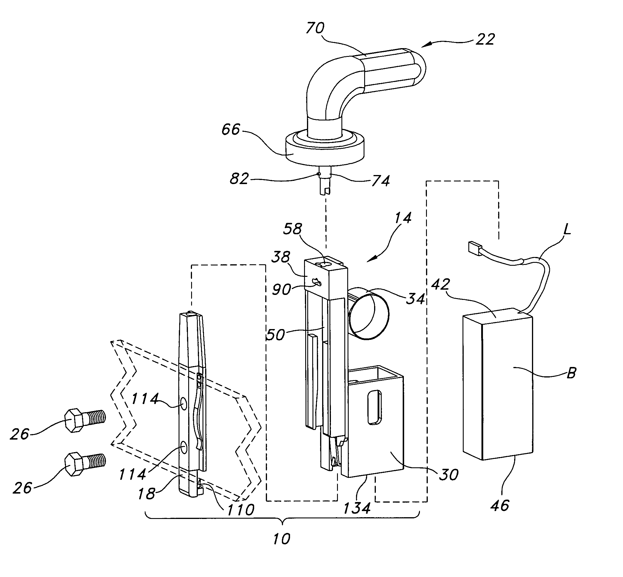
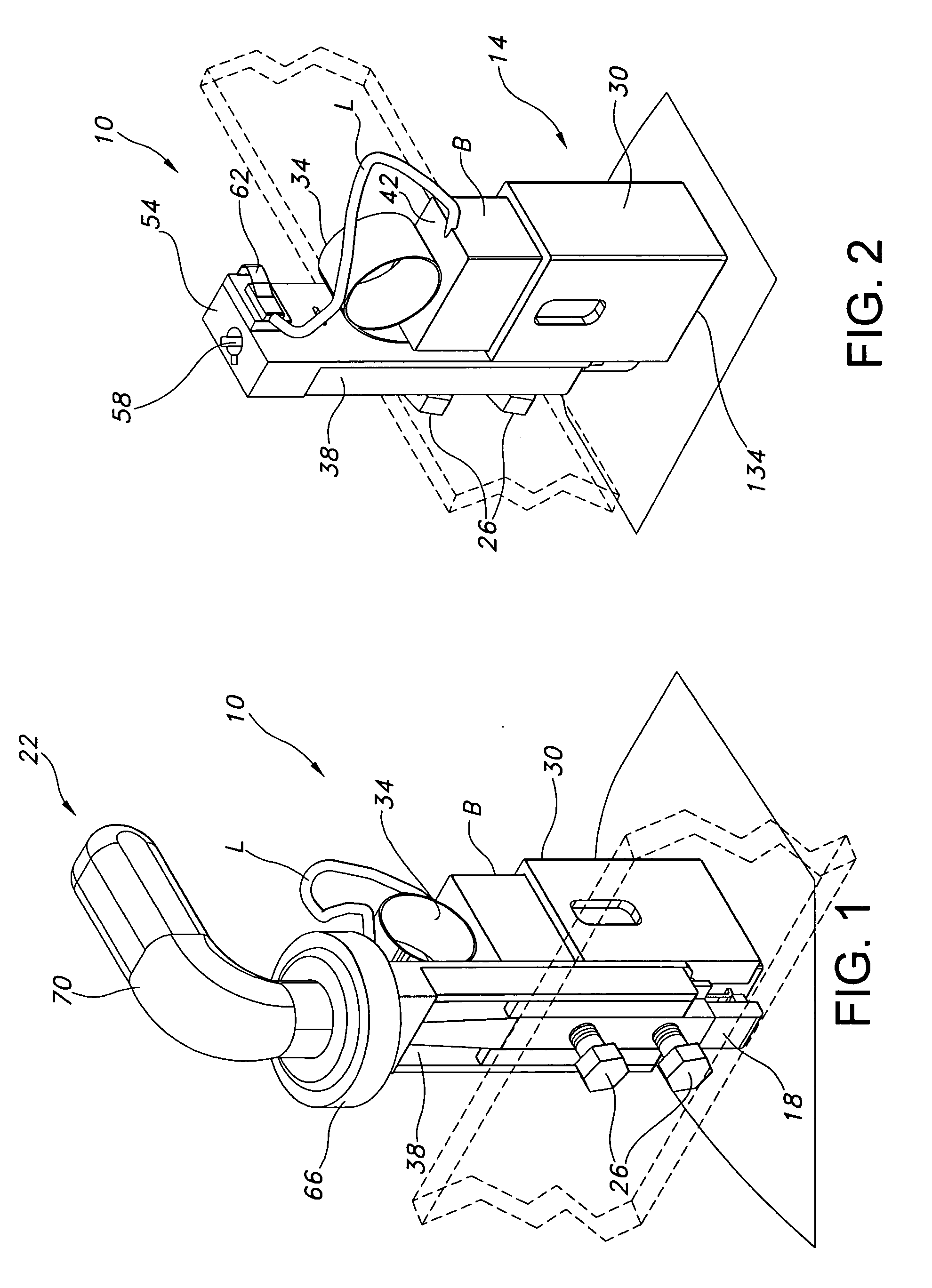
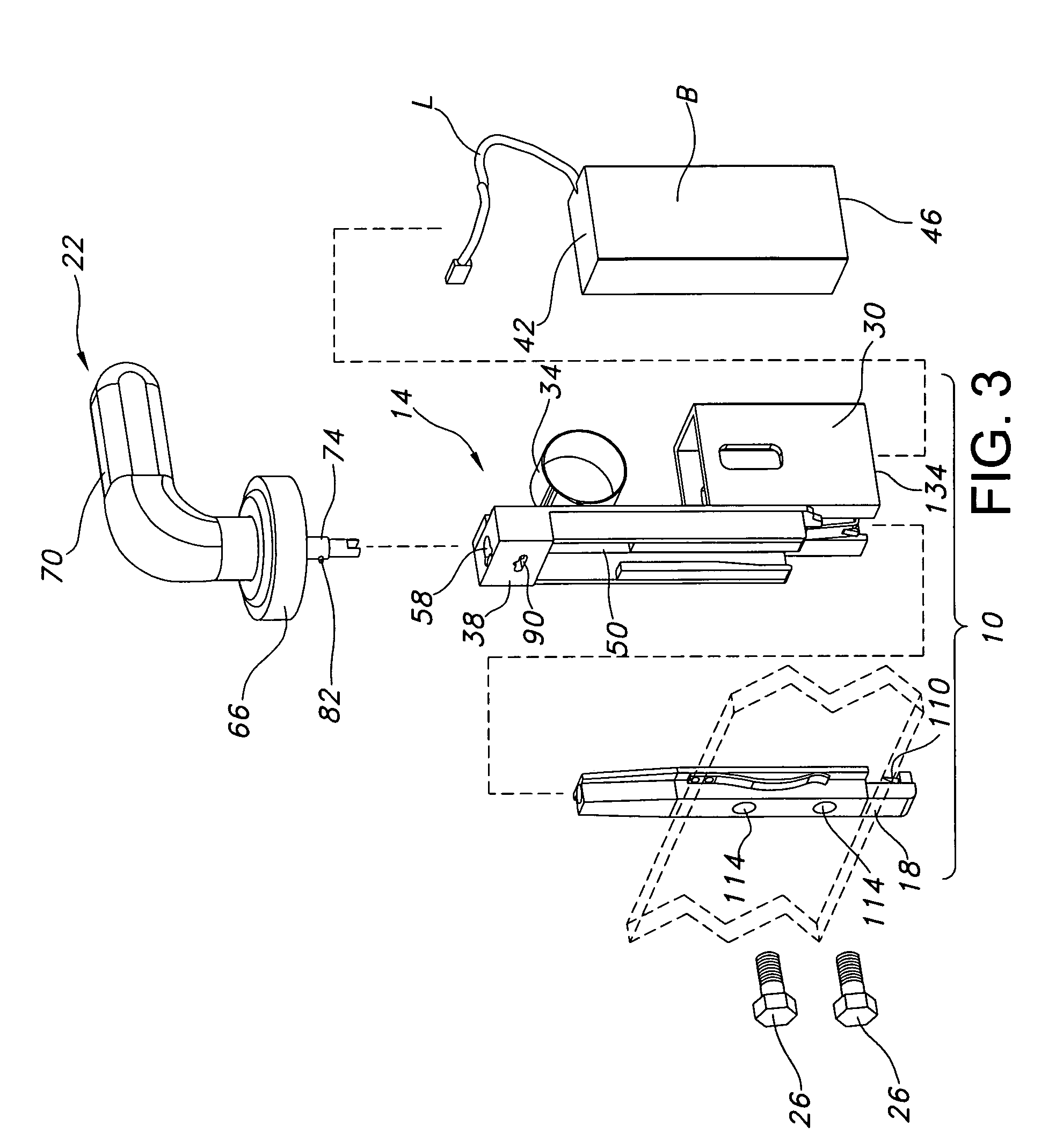
[0021]Detailed in FIGS. 1-4 is brush holder assembly 10 of the present invention. Assembly 10 comprises brush holder 14 and support 18. At times, it additionally may comprise handle 22 and one or more fasteners such as bolts 26. In use, assembly 10 is configured to receive and retain brush B while biasing the brush B toward a surface of a rotating device such as a commutator or slip ring.

[0022]Included as part of holder 14 are brush box 30, spring 34, and back plate or section 38. Box 30 is designed to receive at least a portion of brush B and to support and restrain some movement of the brush B during operation. It preferably is integrally formed with section 38, although it need not necessarily be so formed. Instead, for example, box 30 may be a separate component fastened or otherwise connected to section 38. Holder 14 additionally may be configured to accommodate various forms and dimensions of boxes presently in use in OEM holders.

[0023]Spring 34, as shown in FIGS. 1-4, may be ...


PUM


Abstract

Brush holder assemblies are detailed. The assemblies permit on-line brush replacement and are interchangeable with devices currently provided by original equipment manufacturers. As well, they allow use of brushes longer than those employed in existing on-line replacement assemblies.

Description

FIELD OF THE INVENTION[0001]This invention relates to brush holders and associated equipment and more particularly, but not exclusively, to brush holder assemblies compatible with existing riggings and which allow safer and easier on-line changes of brushes. The assemblies additionally may permit use of longer brushes than current commercially-available assemblies, increasing the time between brush changes.BACKGROUND OF THE INVENTION[0002]U.S. Pat. No. 4,800,313 to Warner, et al., whose contents are incorporated herein in their entirety by this reference, details examples of brush holders for use with carbon brushes. These holders utilize ribbon springs so as to provide essentially constant biasing force to the brushes. They are, in at least this aspect, conventional, as the use of constant biasing force is known generally to reduce maintenance, prevent performance problems, and increase the useful lives of the brushes.[0003]Commutators or slip rings and associated carbon brushes an...

Claims


Application Information

Patent Timeline
IPC IPC(8): H01R39/38H02K13/00
CPCH01R39/40H02K5/148H01R39/42Y10T29/53143
Inventor EGER, LEO A.PARSLOW, JOHN
Owner WABTEC HLDG CORP
Why Eureka
Try Eureka