Image forming apparatus including a plurality of image bearing members having a speed variation suppression feature

a technology of image bearing member and suppression feature, which is applied in the direction of electrographic process apparatus, instruments, optics, etc., can solve the problems of color misregistration, all rotational phases of the photosensitive drum are not aligned with the ideal position, and suffer from the image forming apparatus of this type. to achieve the effect of reducing the deviation between images

Active Publication Date: 2008-04-29
CANON KK
View PDF10 Cites 83 Cited by
  • Summary
  • Abstract
  • Description
  • Claims
  • Application Information

AI Technical Summary

Benefits of technology

[0016]Accordingly, it is a principal object of the present invention to provide an image forming apparatus with which the speed variations in the image bearing members are suppressed to reduce the deviation among the images.

Problems solved by technology

One of the problems which an image forming apparatus of this type suffers is as follows.
Therefore, it is possible that one or more of the four monochromatic images are formed at the ideal position or positions, color misregistration will result (for example, misregistration between black and cyan image.
Therefore, there arises a deviation between a rotational phase of the flange member which supports and positions the photosensitive drum actually forming the images and a rotational phase of the photosensitive drum driving gear of the main assembly side of the apparatus, with the result that all of the rotational phases of the photosensitive drum are not aligned with the ideal positions.
Furthermore, there are unit differences among different color parts resulting form combination of parts (difference resulting from differences among the manufactured units.
These factors lead to the possible variations in the speeds of the photosensitive drums, which may result in the color misregistration in the image forming operation.
In such a case, the rotational driving force is less efficient, and the photosensitive drum speed may vary.
Such a method, however, the formation of the detection pattern and the phase correction responsive to the detection require long time, and therefore, the user has to wait for a relatively long time.
In addition, the phase adjustment accuracy in the positional deviation correction using a detection pattern formation is limited, and the phase difference is not completely removed after the correction in some cases.
To solve such a problem, it would be considered to enhance the resolving power of the detection pattern, but if this is done, the time required for the pattern formation becomes longer correspondingly, with the possible result of increased stress imparted to the user.

Method used


Image

  • Image forming apparatus including a plurality of image bearing members having a speed variation suppression feature
  • Image forming apparatus including a plurality of image bearing members having a speed variation suppression feature
  • Image forming apparatus including a plurality of image bearing members having a speed variation suppression feature

Examples


Embodiment Construction

[0038]Hereinafter, the preferred embodiments of the present invention will be described in detail, with reference to the appended drawings. The preferred embodiments of the present invention, which will be described hereafter, are not intended for limiting the scope of the present invention. In other words, the measurements, materials, and shapes of the structural components, and the positional relationship among the structural components, in the following embodiments of the present invention, should be adjusted as necessary in accordance with the structure of an apparatus to which the present invention is applied, and the various conditions under which an apparatus to which the present invention is applied is operated.

(General Description of Image Forming Apparatus)

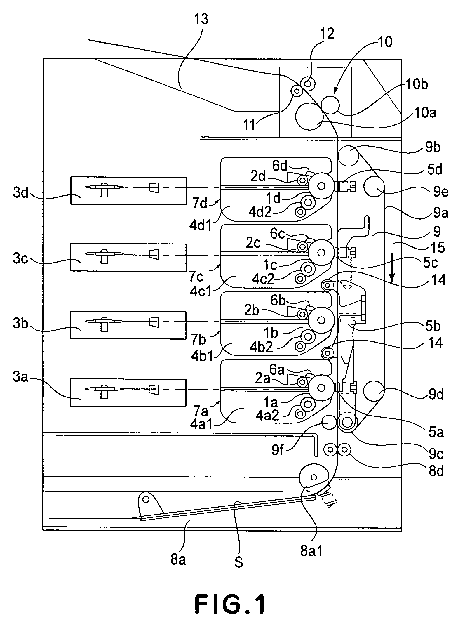
[0039]FIG. 1 is a sectional view of a color image forming apparatus in the preferred embodiments of the present invention, showing the general structure thereof.

[0040]The color image forming apparatus is provided with fo...


PUM


Abstract

An image forming apparatus includes an image bearing member, wherein a toner image is formed on the image bearing member and is transferred onto a recording material, thus forming an image on the recording material; a shaft for rotating the image bearing member, wherein the shaft is provided with a first projection and a second projection, and the image bearing member is provided with a first engaging portion and a second engaging portion which are engageable with the first projection and the second projection, respectively, and wherein the first engaging portion is abuttable to the first projection at downstream and upstream sides of the first projection with respect to a rotational direction of the shaft, and the second engaging portion is abuttable to the second projection at a downstream side of the second projection, and wherein a gap is provided between the second engaging portion and the second projection at an upstream side of the second projection.

Description

FIELD OF THE INVENTION AND RELATED ART[0001]The present invention relates to an image forming apparatus, for example, a copying machine, a printer, or a facsimile machine, having a function of forming an image on recording medium in the form of a sheet or the like. In particular, it relates to the driving of an image bearing member with which an image forming apparatus is provided.[0002]In recent years, demand has been increasing for an electrophotographic image forming apparatus capable of forming a color (multicolor) image; there has been a strong desire for a color image forming apparatus capable of satisfying the following six requirements: (1) being low in operational cost, (2) small in size, (3) low in power consumption, (4) high in image quality, (5) high in operational speed, and better in operability.[0003]There are some technologies for providing an image forming apparatus which satisfies some the abovementioned requirements. One of such technologies improves an image form...

Claims


Application Information

Patent Timeline
Patent Type & Authority Patents(United States)
IPC IPC(8): G03G15/00
CPCG03G15/757G03G2215/00075
Inventor HOASHI, SHIGERUCHADANI, KAZUO
Owner CANON KK
Why Eureka
Try Eureka