Dishwasher vent assembly

a technology for vents and dishwashing machines, applied in drying machines, circuit breakers, lighting and heating apparatus, etc., can solve the problems of increasing the complexity of manufacturing the vent, and reducing the efficiency of the ven

Inactive Publication Date: 2008-05-06
ILLINOIS TOOL WORKS INC
View PDF8 Cites 16 Cited by
  • Summary
  • Abstract
  • Description
  • Claims
  • Application Information

AI Technical Summary

Benefits of technology

[0011]The present invention employs a cam drive mechanism moving a valve plate within a dishwasher vent without the need for a direct connection between an actuator and the shaft about which the valve plate rotates. This approach allows the valve plate shaft to be retained wholly within the vent housing eliminating leaks along a rotating shaft passing through the housing or excess shaft friction, and allowing the vent housing to be molded or preassembled as one piece with the valve plate is snapped into place subsequent to the molding.
[0012]The drive mechanism allows the axis of the valve plate and the drive actuator (preferably a wax motor) to be parallel and closely adjacent to the valve plate pivot axis, providing an extremely compact mechanism that may fit easily between the front and rear panel of a dishwasher door. This advantage also applies to an embodiment in which the valve plate is supported by externally inserted pins or the like.
[0013]In one embodiment, the cam mechanism may open and close the valve plate without the need for a biasing spring element or reliance on gravity, and may accommodate over travel common in wax motors while still providing a large amount of mechanical amplification to fully open and close the valve plate with small amounts of actuator travel.
[0014]In one embodiment, the operator may extend along an axis parallel to, but displaced from, a pivot axis of the valve plate to provide an extremely compact assembly.

Problems solved by technology

Dishwashers can be loud, particularly during the washing cycle, with noise coming from the agitated water, movement of the dishes, and the dishwasher mechanism of pump and motor.
Some of this noise can be reduced by properly shrouding the washing chamber with acoustically absorbent material, nevertheless, even with a properly shrouded chamber, a substantial amount of noise can escape through the vent by diffraction.
Both of these approaches increase the complexity of manufacturing the vent: the former requiring assembly of the shaft and vent plate from inside of the vent, and the latter requiring assembly of the vent housing from several pieces.

Method used


Image

  • Dishwasher vent assembly
  • Dishwasher vent assembly
  • Dishwasher vent assembly

Examples


Embodiment Construction

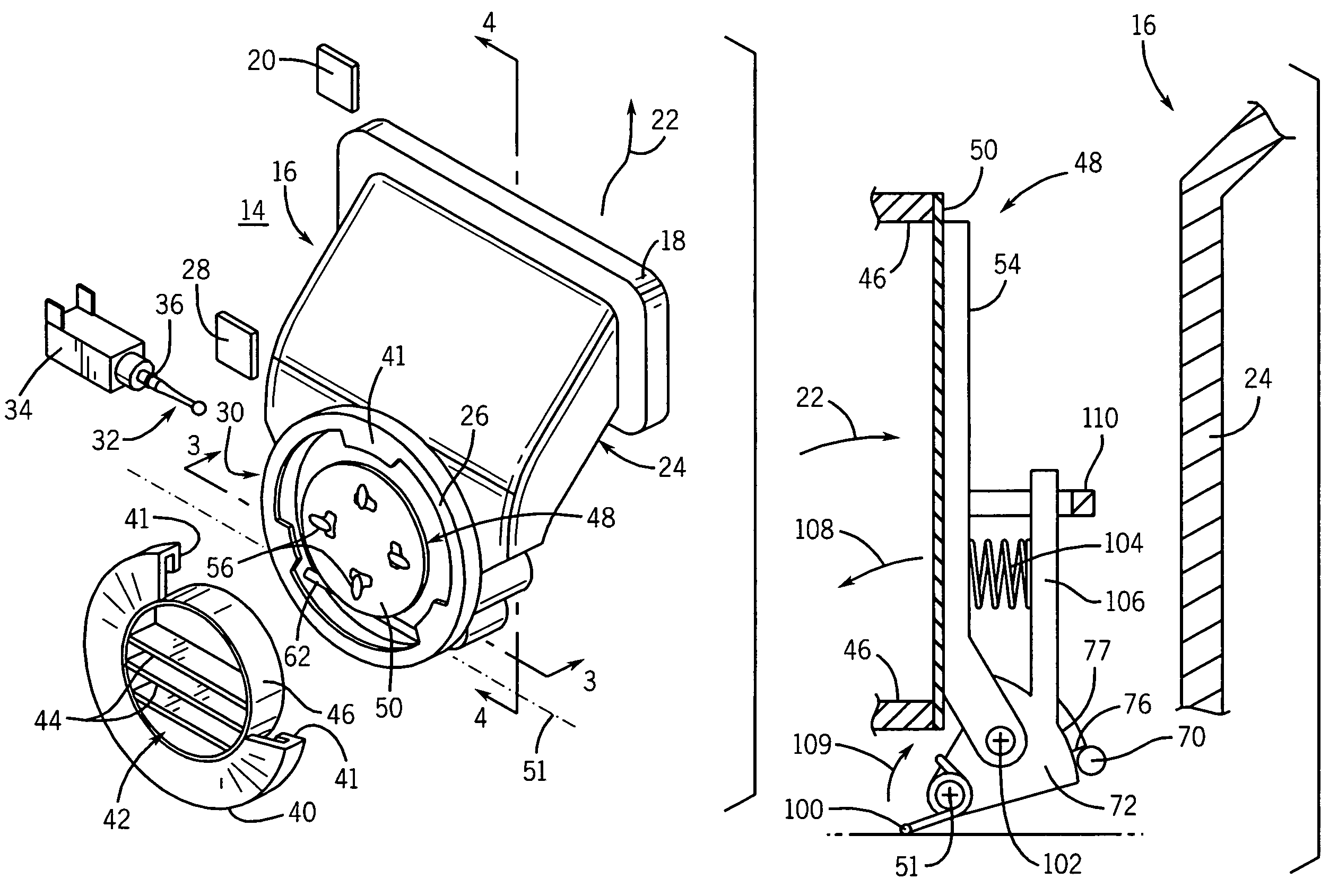
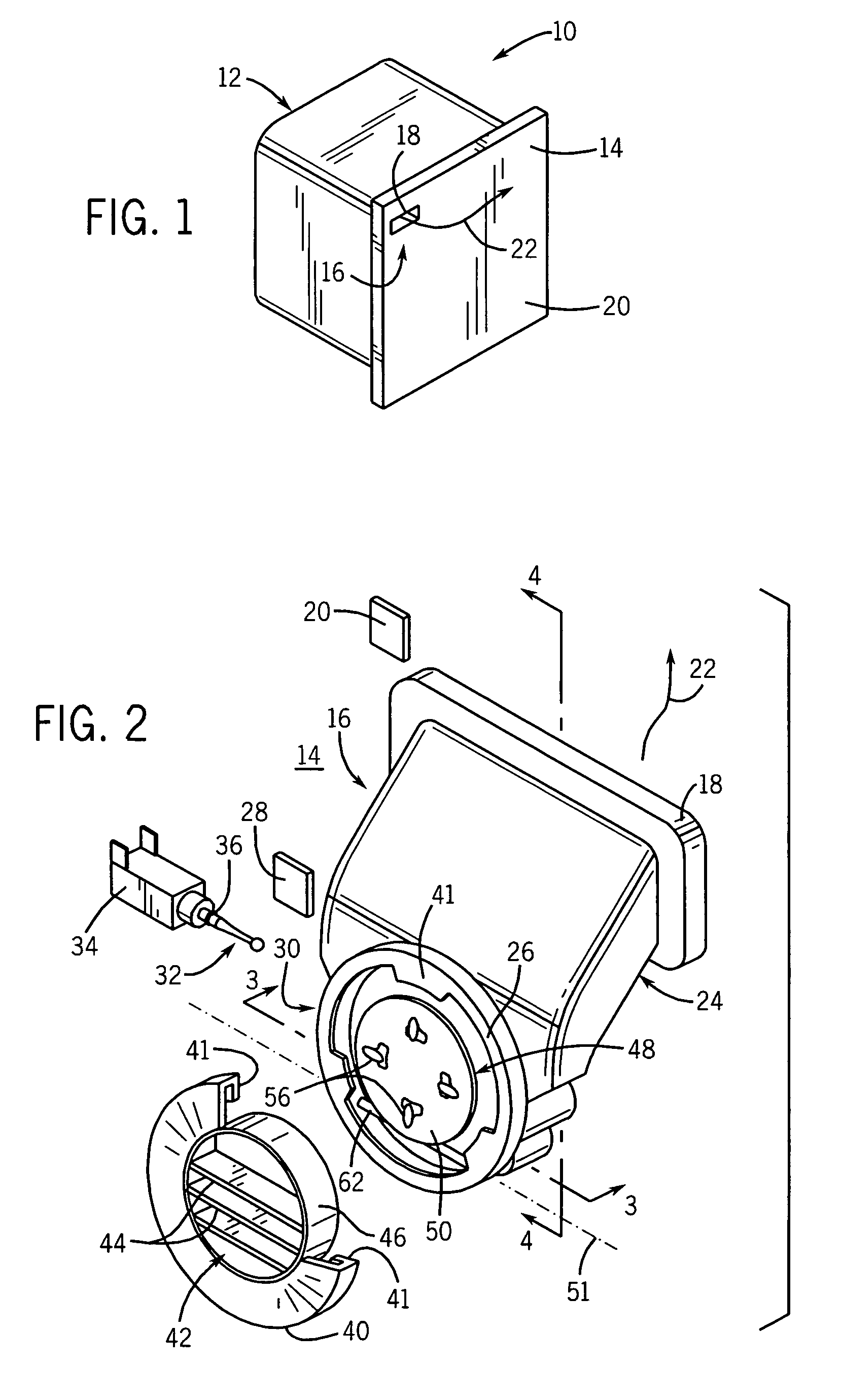
[0026]Referring now to FIG. 1, a dishwasher 10 may include a housing 12 holding a washing chamber and a front door 14 that may be opened to obtain access to the washing chamber for loading and unloading of dishes. A door vent 16 provides an outlet port 18 in the front surface 20 of the door 14 to allow for the escape of moist air 22.

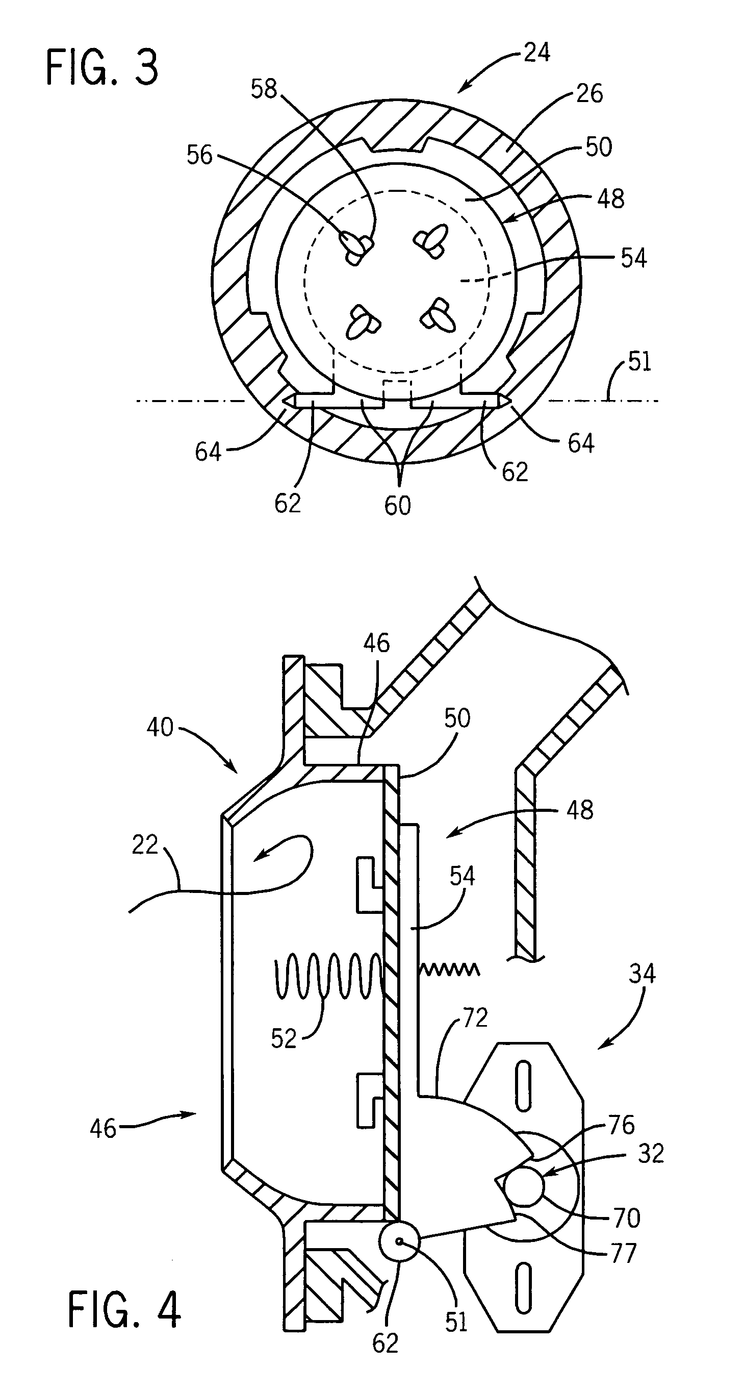
[0027]Referring now to FIG. 2, a vent housing 24 provides an air passage between the outlet port 18 on the front surface 20 and an inlet port 26 opening at the rear surface 28 of the door 14 facing the washing chamber. The outlet port 18 is positioned higher on the door than the inlet port 26, both to provide a serpentine path for muting sound passing through the vent housing 24 and to cause water splashed into and condensation forming within the vent housing to drain downward out of inlet port 26 back into the wash chamber. Preferably, the vent housing 24 is manufactured as a single injection molded part avoiding a need for subsequent assembly of multip...


PUM


Abstract

A mechanized vent for a dishwasher employs a vent plate moving about a hinge axis as driven by a cam mechanism at a surface of the vent plate removed from the hinge axis.

Description

CROSS-REFERENCE TO RELATED APPLICATIONS[0001]This application claims the benefit of U.S. Provisional application 60 / 579,883 filed Jun. 15, 2004, and hereby incorporated by reference.STATEMENT REGARDING FEDERALLY SPONSORED RESEARCH OR DEVELOPMENTBACKGROUND OF THE INVENTION[0002]The present invention relates to automatic dishwashing machines (dishwashers) and in particular to a dishwasher vent for use in a low noise dishwasher.[0003]Dishwashers, such as those found in many homes, provide a chamber holding one or more racks into which eating utensils and cookware may be placed for cleaning. The chamber may be closed by a door opening at the front of the chamber to allow loading and unloading of the chamber.[0004]The door is closed during a washing cycle to prevent the escape of water sprayed within the volume of the chamber to wash items placed in the rack. Upon completion of the washing cycle, a drying cycle is initiated during which water is drained from the chamber and moist air is ...

Claims


Application Information

Patent Timeline
Patent Type & Authority Patents(United States)
IPC IPC(8): F26B19/00D06F58/20F26B25/06
CPCA47L15/488D06F58/20A47L15/0052Y10T137/785
Inventor OSVATIC, MICHAEL S.HINTZ, MICHAEL K.BRAGG, JOEL C.KRIEGER, JEFFREY J.RODAER, MARK D.
Owner ILLINOIS TOOL WORKS INC
Why Eureka
Try Eureka