Universal fixed pin trigger block

a technology of trigger block and pin, applied in the field of trigger lock, can solve the problems of high cost and inconvenience, and achieve the effect of cost saving

Active Publication Date: 2008-05-06
REGAL PROD LLC
View PDF23 Cites 22 Cited by
  • Summary
  • Abstract
  • Description
  • Claims
  • Application Information

AI Technical Summary

Benefits of technology

[0008]As will be appreciated, it is necessary or beneficial for gun manufacturers and others to provide locks with all firearms sold. And, it is extremely advantageous for them to be able to purchase and stock a lock that will fit a whole family or type of firearm for a manufacturer as opposed to having to buy and maintain an inventory of individualized locks for each firearm sold. The logistics and difficulty of maintaining (and neither over buying nor under buying) locks that can be used for only a single firearm can lead to costly waste and a great deal of inconvenience. Thus, our invention seeks to overcome these problems with a lock that has multiple applications for a single manufacturer, is sturdy, durable, cost efficient, meets all applicable standards, and—with the other innovations set forth herein—admirably and efficiently serves the purposes for which it is designed.

Problems solved by technology

The logistics and difficulty of maintaining (and neither over buying nor under buying) locks that can be used for only a single firearm can lead to costly waste and a great deal of inconvenience.

Method used


Image

  • Universal fixed pin trigger block
  • Universal fixed pin trigger block
  • Universal fixed pin trigger block

Examples


Embodiment Construction

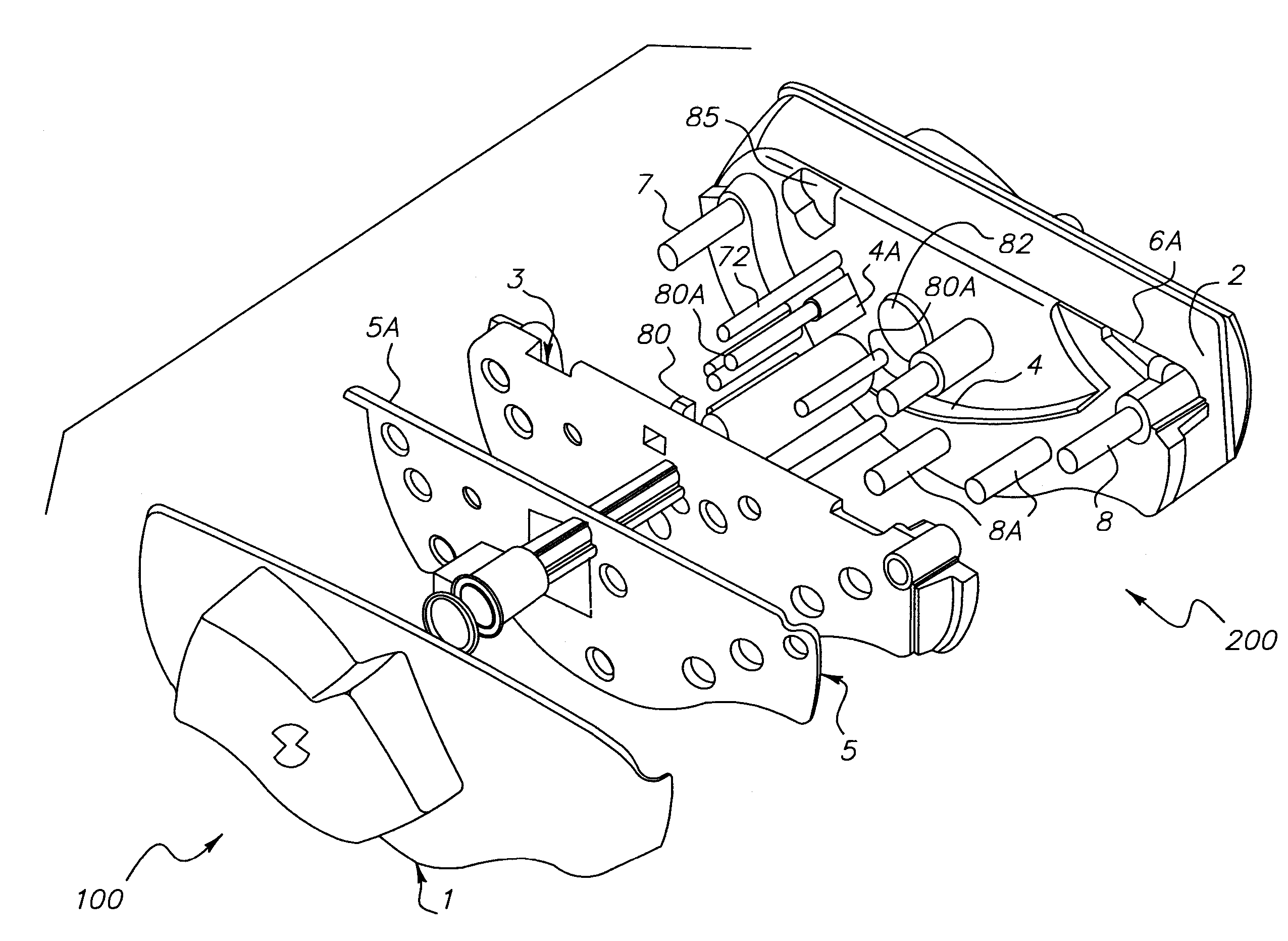
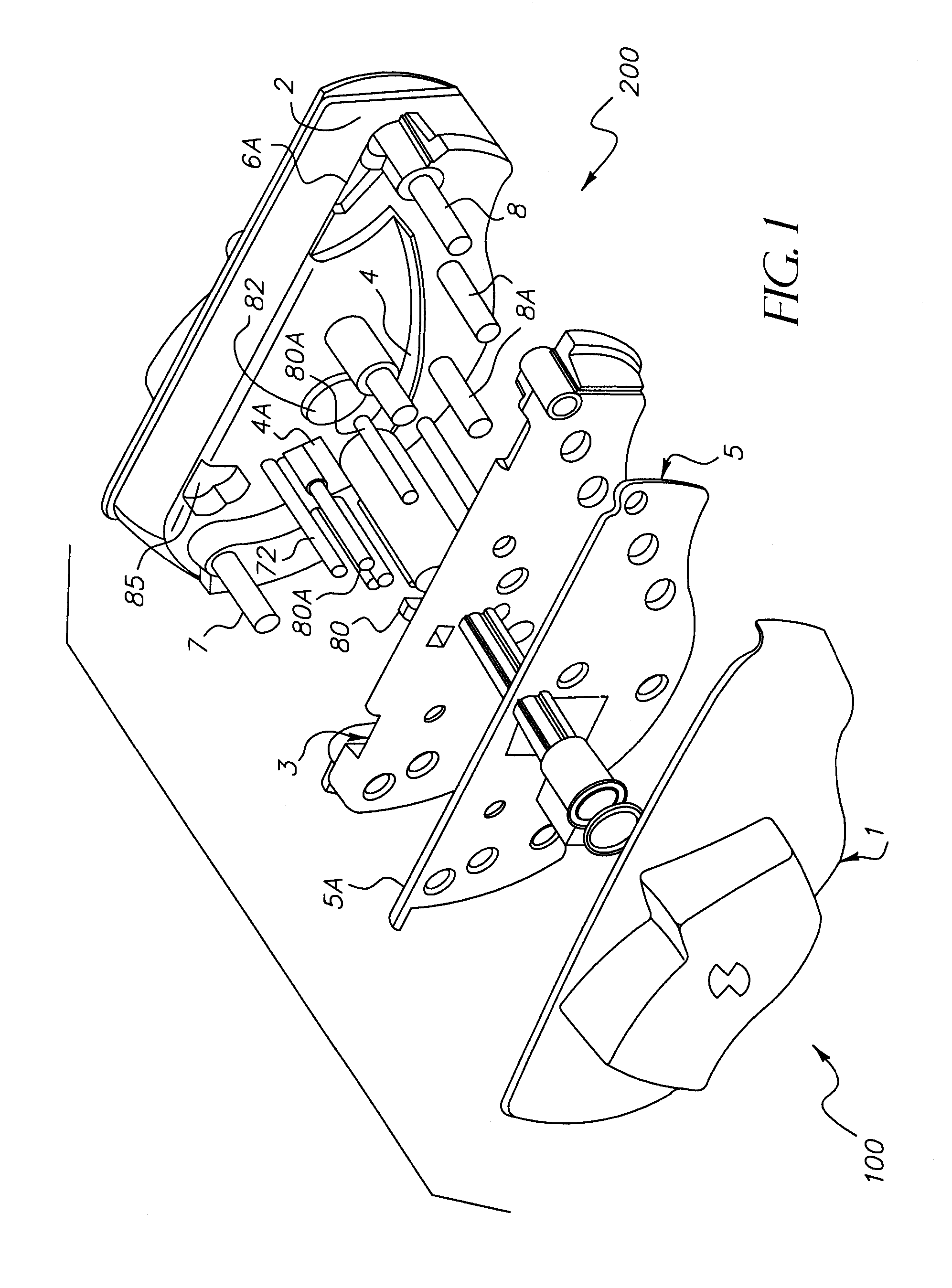
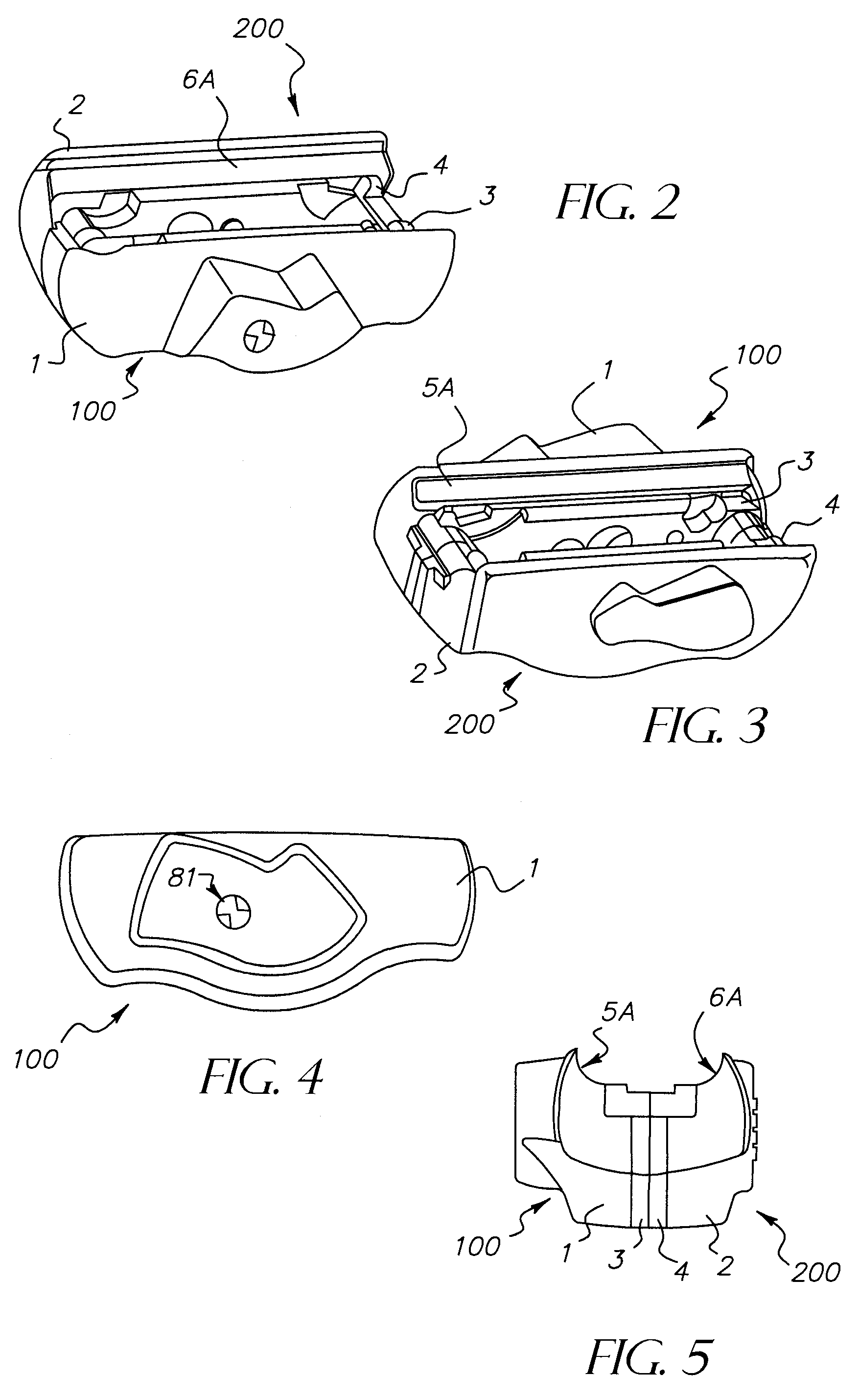
[0019]As will be noted from review of FIGS. 1 through 9, the first preferred embodiment of our invention is comprised of two halves (a right side 100 and a left side 200) that are adapted to fit together over a trigger guard 30 and adjacent the ventral side 40 and lower lateral sides 50, 60 of a firearm (such as illustrated shot gun 70) adjacent the trigger guard 30 of said firearm. The right side 100 includes a zinc die cast right outer housing 1 and the left side, similarly includes a left outer housing 2. Interior of these two housings 1, 2 there are respective polymer interfaces (right interface 3 and left interface 4) formed from, preferably, a sturdy polymer such as 90 Dura Santoprene®.

[0020]Right interface 3 and left interface 4 are adapted for non-damaging contact with portions of the trigger guard 30, ventral side 40, and lateral sides 50, 60 of a firearm such as shot gun 70. Sandwiched between these respective outer and inner portions of sides 1, 2 are, respectively, a rig...


PUM


Abstract

A firearm trigger locking device with two sides and fixed hardened steel pins. The device is designed to be universal for a particular family of guns—e.g., all rifles, all shotguns, or all handguns (or all revolvers or automatic pistols)—of a given firearm manufacturer. The device further features a pin behind the trigger to prevent firing, hardened steel plates in each side sufficient in size to cover the trigger guard and prevent transverse application of a saw to the trigger guard, and a ring of hardened steel pins around the periphery of the trigger guard to prevent application of a saw between the plates. The method for producing this trigger locking device uses lateral and axial profiles of the family of firearms to develop features and feature locations that will allow it to be used with any member of the family of firearms.

Description

REFERENCE TO RELATED APPLICATIONS[0001]This application claims an invention which was disclosed in Provisional Application No. 60 / 635,128, filed Dec. 10, 2004, entitled “Universal Fixed Pin Trigger Lock”. The benefit under 35 USC §119(e) of the United States provisional application is hereby claimed, and the aforementioned application is hereby incorporated herein by reference.BACKGROUND OF THE INVENTION[0002]1. Field of the Invention[0003]The invention pertains to the field of trigger locks for firearms. More particularly, the invention pertains to a trigger lock with fixed pins designed to fit a family of firearms.[0004]2. Description of Related Art[0005]Gun manufacturers generally provide some type of trigger lock or gunlock with new firearms. Numerous locks have been developed for this purpose. Cable locks use lengths of cable extending / threaded through the action of the weapon, blocking usage. Another type of lock is the trigger guard plate lock. The trigger guard plate lock us...

Claims


Application Information

Patent Timeline
Patent Type & Authority Patents(United States)
IPC IPC(8): F41A17/54
CPCF41A17/54
Inventor FARCHIONE, THOMAS JOSEPHFARCHIONE, JR., PATRICK
Owner REGAL PROD LLC
Why Eureka
Try Eureka