Recording medium transfer apparatus

a transfer apparatus and recording medium technology, applied in the direction of thin material processing, printing, article separation, etc., can solve the problems of reducing the stackability, reducing the transfer speed of the recording medium, and increasing the rotation speed of the discharge roller, so as to improve the transfer throughput and be easy to judg

Inactive Publication Date: 2008-05-06
SEIKO EPSON CORP
View PDF7 Cites 8 Cited by
  • Summary
  • Abstract
  • Description
  • Claims
  • Application Information

AI Technical Summary

Benefits of technology

[0011]Accordingly, in the recording medium transfer apparatus, while the recording medium which will be recorded next is being fed to the liquid ejection area, the recording medium on which recording has been finished is prevented from being discharged out of the discharge roller at high speed. Therefore, the rear end of the recording medium is discharged at lower speed than the feed speed. Thus, the recording medium transfer apparatus can obtain the stackability the discharged recording medium as well as improving the transfer throughput.
[0012]The recording medium transfer apparatus may further include a recording medium sensor disposed at the predetermined position for detecting the recording medium, wherein the feed control unit controls the next recording medium to be fed simultaneously with discharge of the recording medium, if the recording medium sensor detects the recording medium when recording or printing has been finished, whereas controlling the next recording medium to be fed after discharge of the recording medium has been finished, if the recording medium sensor does not detect the recording medium when recording or printing has been finished. Accordingly, it is possible to easily judge whether the next recording medium should start to be fed or not based on the detection result by the recording medium sensor.
[0013]The recording medium transfer apparatus may further include a roller lock mechanism driven by the motor for preventing the feedroller from being rotated by the motor or stopping rotation prevention of the feed roller by reverse rotation of the motor, wherein when the motor rotates forward, the feed and discharge rollers are rotated in such direction that the recording medium is transferred forward, and the feed control unit uses, as the predetermined position, a position situated further downstream of the feed start position of the next recording medium than a sum of a reverse transfer amount by which the recording medium is transferred reversely due to the reverse rotation of the motor while the rotation prevention is being stopped and width of the liquid ejection area in a transfer direction of the recording medium. Accordingly, the rear end of the recording medium on which recording has been finished and the front end of the recording medium which will be recorded next are not overlapped during transfer, and when recording starts to be performed on the next recording medium, it is prevented that liquid is unnecessarily ejected onto the rear end of the recording medium on which recording has been finished.
[0015]Accordingly, since it is prevented that the rear end of the recording medium on which recording has been finished and the front end of the recording medium which will be recorded next are overlapped during transfer, and that when recording starts to be performed on the next recording medium, liquid is unnecessarily ejected onto the rear end of the recording medium on which recording has been finished, the transfer throughput can be improved.
[0016]The recording medium transfer apparatus may further include a recording medium sensor disposed further downstream of the feed start position of the next recording medium than a sum of the reverse transfer amount and the width of the liquid ejection area in the transfer direction of the recording medium for detecting the recording medium, wherein the feed control unit controls the next recording medium to be fed simultaneously with discharge of the recording medium, if the recording medium sensor does not detect the recording medium when recording or printing has been finished, where as controlling the next recording medium to start to be fed after discharge of the recording medium has been finished, if the recording medium sensor detects the recording medium when recording or printing has been finished. Accordingly, it is possible to easily judge whether the next recording medium should start to be fed or not based on the detection result by the recording medium sensor.

Problems solved by technology

However,the transfer speed of the recording medium is restricted depending on the operation state of the liquid ejecting apparatus.
If the discharge speed of the recording medium exceeds the specific value, the electrostatic force caused by electrification of the recording medium mainly decreases the stackability.
In this case, when the rotation speed of the feed roller becomes high to improve the throughput, the rotation speed of the discharge roller also becomes high, so there is such a problem that the stackability cannot be obtained.

Method used


Image

  • Recording medium transfer apparatus
  • Recording medium transfer apparatus
  • Recording medium transfer apparatus

Examples


Embodiment Construction

[0031]The invention will now be described based on the preferred embodiments, which do not intend to limit the scope of the present invention, but exemplify the invention. All of the features and the combinations thereof described in the embodiment are not necessarily essential to the invention.

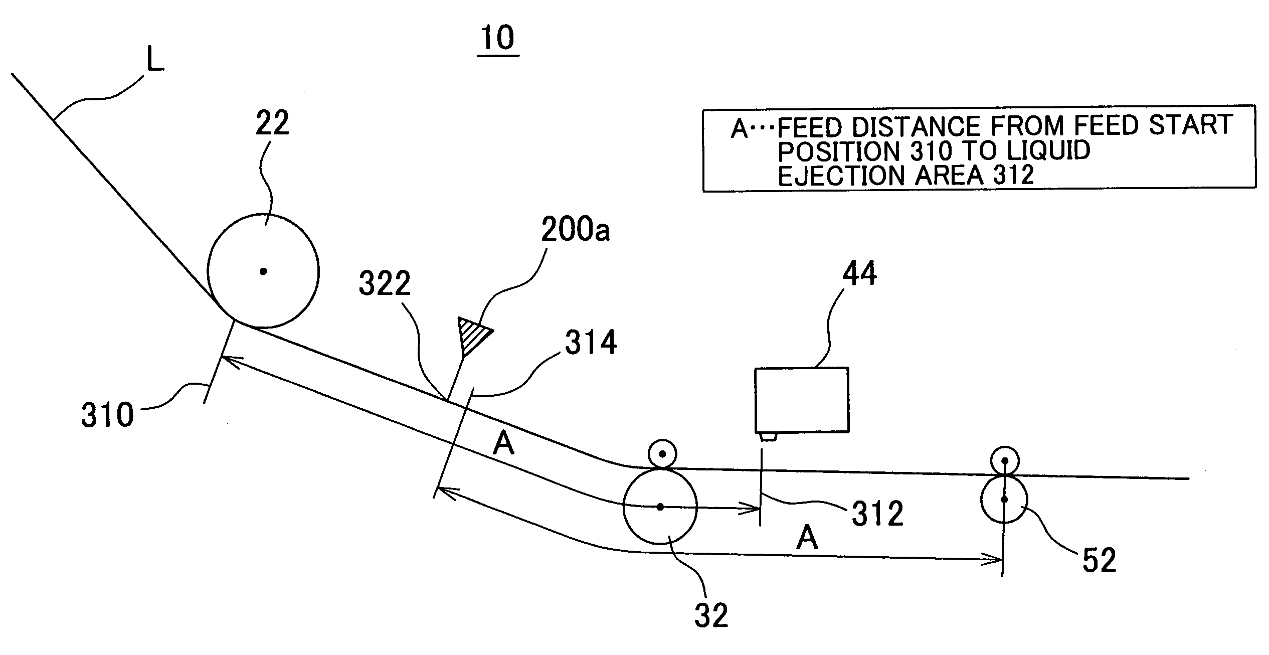
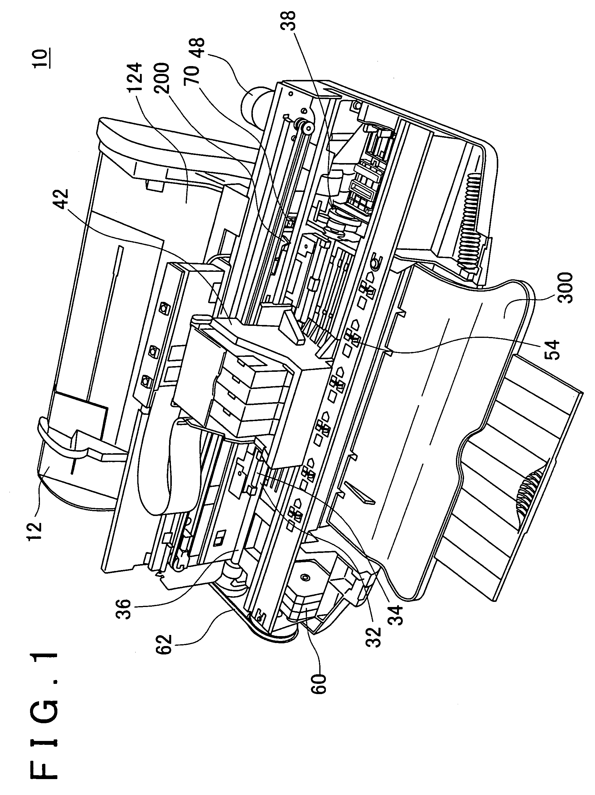
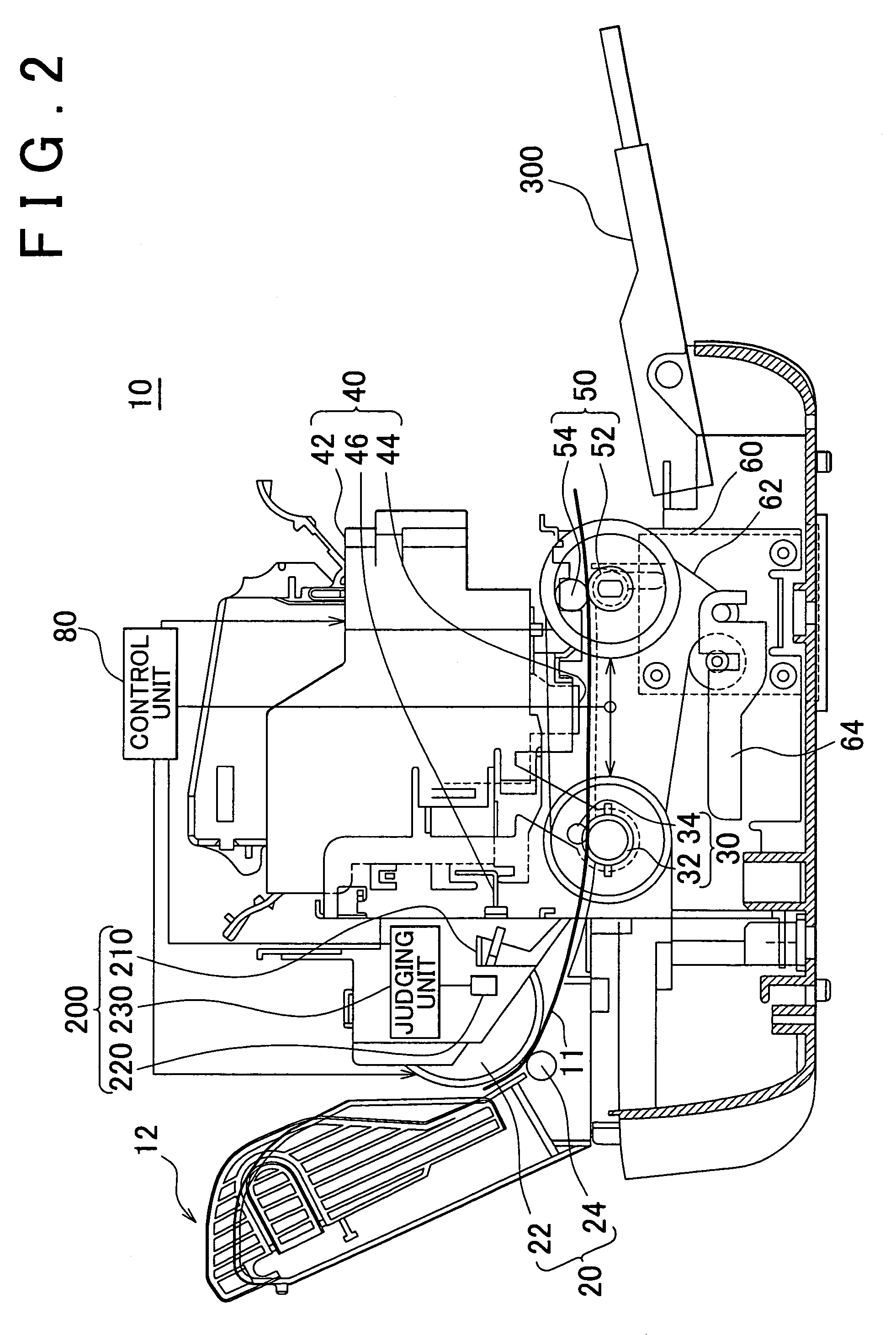
[0032]FIG. 1 shows a perspective view of an inkjet type recording apparatus 10 which is an example of a liquid ejecting apparatus. The inkjet type recording apparatus 10 of this embodiment includes a recording medium transfer apparatus therein. The recording medium transfer apparatus includes a feed roller for feeding recording mediums towards a liquid ejection area, a discharge roller for discharging the recording mediums on which recording or printing has been finished out of the liquid ejection area, and a step motor 60 for driving the feed and discharge rollers. When the recording medium transfer apparatus feeds the recording medium to the liquid ejection area, it allows the step motor 60...


PUM


Abstract

A recording medium transfer apparatus includes a motor control unit for controlling the motor to rotate at higher speed when the recording medium is fed to the liquid ejection area than that when the recording medium is discharged out of the liquid ejection area, and a feed control unit for controlling a next recording medium to be fed simultaneously with discharge of the recording medium, if a position of a rear end of the recording medium when recording or printing has been finished is situated upstream of a predetermined position, which is upstream of the discharge roller as much as a distance between a feed start position of the recording medium and the liquid ejection area, whereas controlling the next recording medium to start to be fed after discharge of the recording medium has been finished, if the position of the rear end of the recording medium when recording or printing has been finished is situated downstream of the predetermined position.

Description

[0001]This patent application claims priority from a Japanese patent application No. 2003-123776 filed on Apr. 28, 2003, the contents of which are incorporated herein by reference.BACKGROUND OF THE INVENTION[0002]1. Field of the Invention[0003]The present invention relates to a recording medium transfer apparatus. More particularly, the present invention relates to a recording medium transfer apparatus for transferring a recording medium on which recording or printing is performed by ejecting liquid to a liquid ejection area where the liquid is ejected onto the recording medium.[0004]2. Description of the Related Art[0005]A liquid ejecting apparatus such as an inkjet type recording apparatus includes a recording medium transfer apparatus. In order to improve the recording throughput of the liquid ejecting apparatus, it is effective to increase the speed of transferring the recording medium by the recording medium transfer apparatus. However,the transfer speed of the recording medium...

Claims


Application Information

Patent Timeline
Patent Type & Authority Patents(United States)
IPC IPC(8): B65H7/08B41J13/02B41J13/00B65H5/06
CPCB41J13/0009
Inventor YOSHIHISA, YASUHIKONOBUTA, KOSAKU
Owner SEIKO EPSON CORP
Why Eureka
Try Eureka