Noncontact temperature measurement device having compressed video image transfer

Active Publication Date: 2008-05-06
RAYTEK
View PDF6 Cites 19 Cited by
  • Summary
  • Abstract
  • Description
  • Claims
  • Application Information

AI Technical Summary

Problems solved by technology

To transmit a real-time image to the remote computer, an extra cable is required for the video signal because the bandwidth of the standard (RS232 / RS485) protocol is too small for video data.

Method used


Image

  • Noncontact temperature measurement device having compressed video image transfer
  • Noncontact temperature measurement device having compressed video image transfer
  • Noncontact temperature measurement device having compressed video image transfer

Examples


Embodiment Construction

[0021]It is to be understood by one of ordinary skill in the art that the present discussion is a description of exemplary embodiments only, and is not intended as limiting the broader aspects of the present invention, which broader aspects are embodied in the exemplary constructions.

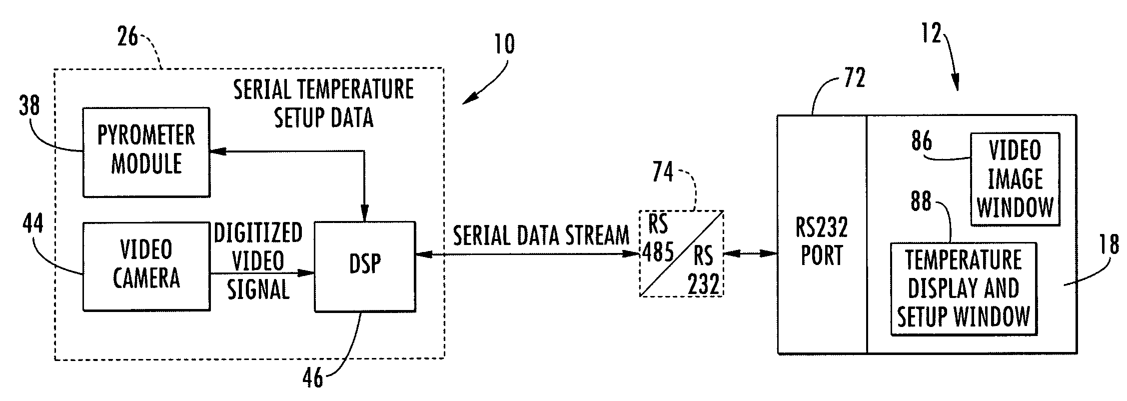
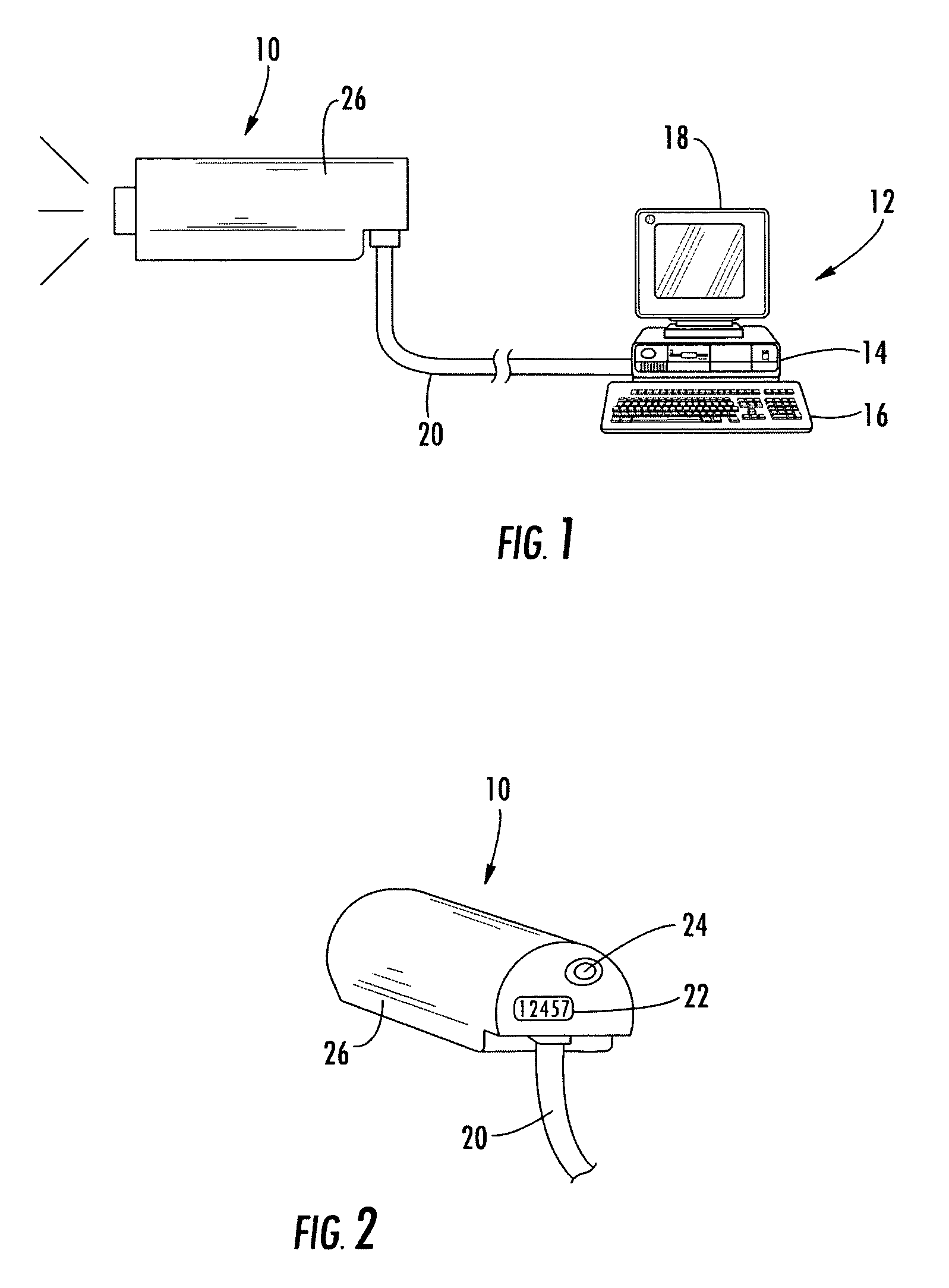
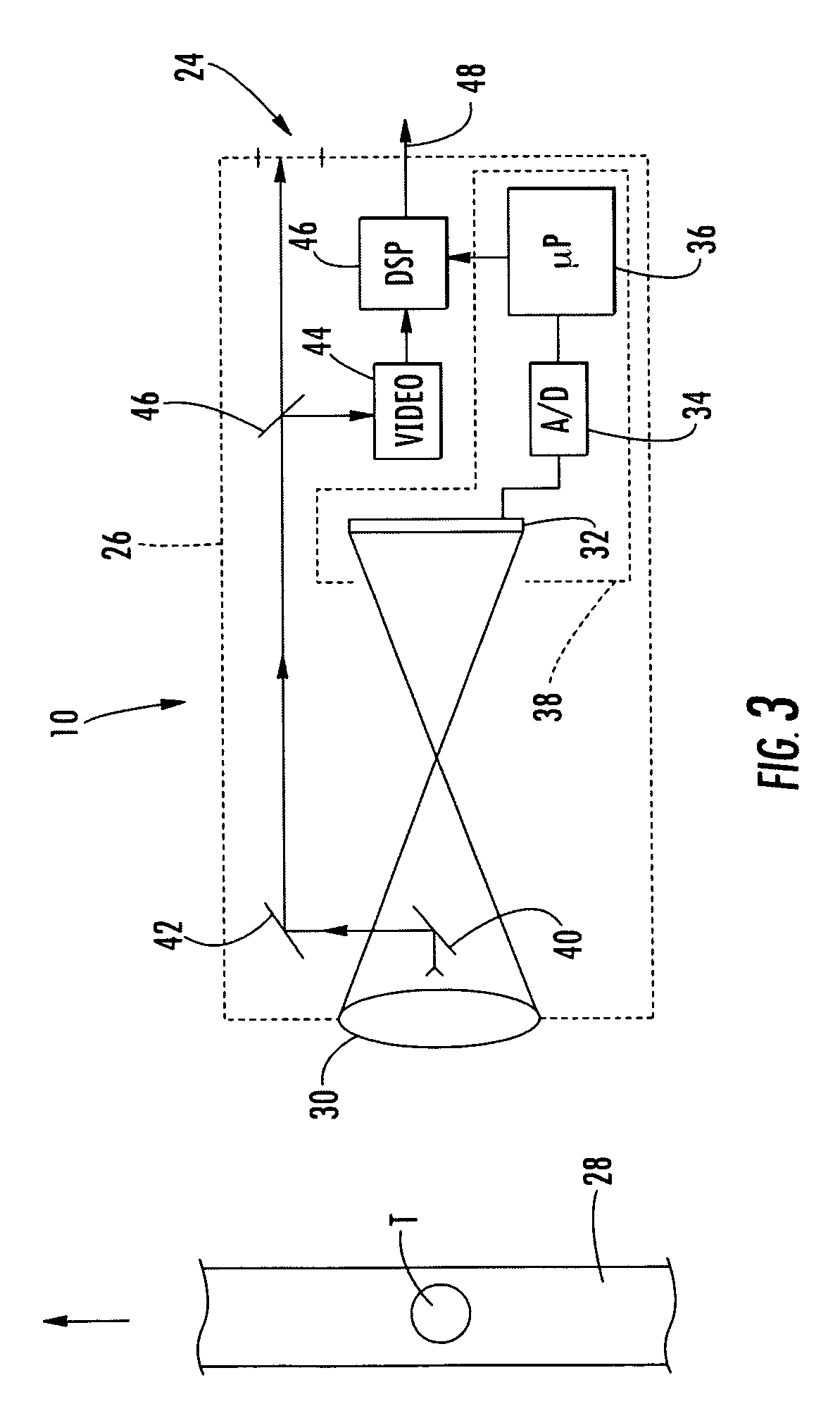
[0022]FIG. 1 illustrates a pyrometer 10 situated at a first location to determine temperature of a selected target. Pyrometer 10 includes an internal detector which collects energy radiated from the target, as defined by the device's optics and location. The energy, typically in the form of infrared (IR) radiation, is isolated and focused on the detector. The detector converts the energy into an electrical signal which is then internally processed to yield a temperature value. In many embodiments, for example, pyrometer 10 will be situated to detect temperature fluctuations occurring in a manufacturing environment or other industrial process.

[0023]In the illustrated embodiment, pyrometer 10 is in electr...


PUM


Abstract

An apparatus for measuring temperature comprises a noncontact temperature measurement device situated at a first location. The device includes a sensor operative to collect radiant energy emanated from a target. Circuitry associated with the sensor produces a digital temperature signal containing temperature data regarding the target. A video camera produces a digital video signal containing video data of the target. A processor receives the digital temperature signal and the digital video signal and produces a combined digital signal for transmission to a second location. The combined digital signal contains both the temperature data and the video data. A computer situated at the second location receives the combined digital signal and separates the temperature data from the video data. Preferably, the computer includes a display having two windows on which the temperature data and the video data are respectively shown.

Description

BACKGROUND OF THE INVENTION[0001]The present invention relates generally to noncontact temperature measurement devices (pyrometers). More particularly, the invention relates to a pyrometer having a video sighting feature which transfers video and temperature data to a remote computer.[0002]Pyrometers are used in a wide variety of applications. For example, handheld infrared (IR) pyrometers allow a user to ascertain the temperature of a target using a point and click technique. These devices are commonly utilized for purposes ranging from automotive diagnostics to food safety.[0003]In other applications, it is desirable to use a stationary pyrometer having some local processing capability. The pyrometer in such cases will generally be connected to a remote computer with which it is in two-way digital communication. Typically, the two-way communication will be provided by common RS485 or RS232 protocols. Such an arrangement can be used, for example, in various process control environm...

Claims


Application Information

Patent Timeline
IPC IPC(8): H04N7/18
CPCG01J5/02G01J5/025G01J5/0265G01J5/08G01J5/0846H04N7/183G01J2005/0077G01J2005/0081G01J5/48
Inventor HEINKE, THOMASSCHNEIDER, FRANK W.WARNKE, STEFAN H.
Owner RAYTEK
Why Eureka
Try Eureka