Connector switch

a technology of connecting switch and oximetry, which is applied in the direction of coupling device connection, diagnostic recording/measuring, diagnostics, etc., can solve the problems of monitor status message and sensor malfunction

Active Publication Date: 2008-05-13
JPMORGAN CHASE BANK NA
View PDF114 Cites 762 Cited by
  • Summary
  • Abstract
  • Description
  • Claims
  • Application Information

AI Technical Summary

Problems solved by technology

In some circumstances, however, removing the sensor from such an adapter cable can result in a monitor status message indicating a malfunctioning sensor rather than a disconnected sensor.
This arises because the monitor is able to read the information element but is unable to receive a detector signal.

Method used


Image

  • Connector switch
  • Connector switch
  • Connector switch

Examples


Embodiment Construction

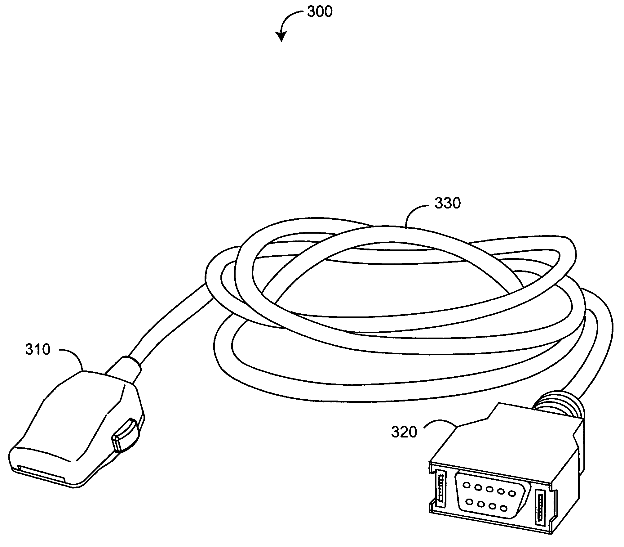
[0025]FIGS. 3-4 illustrate an adapter patient cable 300 having a sensor connector 310 and a monitor connector 320 physically and electrically connected by a cable 330. The sensor connector 310 has a resistor 410 (FIG. 4) and a normally open (N.O.) switch 420 (FIG. 4) in series with the resistor 410. The resistor 410 functions as a sensor information element, as described above. The switch 420 is responsive to a sensor being attached or removed from the sensor connector 310, as described below. Utilizing the switch 420 to connect and disconnect the resistor advantageously allows a connected monitor to indicate accurate status information regarding a sensor.

[0026]In particular, when a sensor is attached to the sensor connector 310, the switch 420 moves to a closed position 522 (FIG. 5B) connecting the resistor 410 to the monitor so that the monitor is able to read the resistor 410. When a sensor is removed from the sensor connector 310, the switch 420 returns to an open position 521 (...


PUM


Abstract

An interconnection between a sensor and a monitor has a cable, an information element and a switch. The cable has conductors providing electrical communication between a sensor connector and a monitor connector. The information element is readable by the monitor and mounted in the sensor connector, the monitor connector or the cable. A switch is mounted in the sensor connector and is responsive to the sensor connecting to and disconnecting from the sensor connector so as to alter the readability of said information element.

Description

CROSS-REFERENCE TO RELATED APPLICATIONS[0001]This application relates to and claims the benefit of prior U.S. Provisional Application No. 60 / 546,531 entitled Connector Switch, filed Feb. 20, 2004 and incorporated by reference herein.BACKGROUND OF THE INVENTION[0002]Pulse oximetry is a widely accepted noninvasive procedure for measuring arterial oxygen saturation, which provides early detection of hypoxia. FIG. 1 illustrates a pulse oximetry system 100 having a sensor 110 applied to a patient, a monitor 120, and a patient cable 130 connecting the sensor 110 and the monitor 120. The sensor 110 has emitters and a detector, which are attached to a tissue site, such as a finger as shown. The patient cable 130 transmits an emitter drive signal from the monitor 120 to the sensor 110 and a resulting detector signal from the sensor 110 to the monitor 120. The monitor 120 processes the detector signal to provide a numerical readout of oxygen saturation and pulse rate.[0003]FIGS. 2A-B illustra...

Claims


Application Information

Patent Timeline
Patent Type & Authority Patents(United States)
IPC IPC(8): H01R33/96A61B5/00
CPCA61B5/14551A61B2562/222A61B2562/226
Inventor ABDUL-HAFIZ, YASSIR
Owner JPMORGAN CHASE BANK NA
Why Eureka
Try Eureka