Reset circuit

a reset circuit and circuit technology, applied in the field of reset circuits, can solve problems such as failure to output a reset signal, problem cannot be solved, reset signal to erroneously reset electronic circuits, etc., and achieve the effect of preventing erroneous res

Inactive Publication Date: 2008-05-13
LAPIS SEMICON CO LTD
View PDF9 Cites 6 Cited by
  • Summary
  • Abstract
  • Description
  • Claims
  • Application Information

AI Technical Summary

Benefits of technology

[0012]Therefore, the present invention has been made in view of the above problems, and it is an object of the present invention to provide a reset circuit, which ensures that a reset signal is output when the supply of a power supply voltage is initiated, or a reset circuit which prevents erroneous reset due to noise after the power supply voltage is stabilized.
[0014]In accordance with another aspect of the present invention, there is provided a reset circuit comprising a reset circuit body for outputting a signal indicating a reset when supply of a power supply voltage is initiated until the power supply voltage reaches a sufficient value and indicating release of the reset after the power supply voltage reaches the sufficient value; and a momentary reset indication elimination circuit, provided subsequent to the reset circuit body, for eliminating a momentary change indicating the reset in the output signal of the reset circuit body when the momentary change occurs in the output signal after the power supply voltage rises.
[0016]In accordance with the first and third aspects of the present invention, it is possible to provide a reset circuit which ensures that a reset signal is output when the supply of the power supply voltage is initiated.
[0017]In accordance with the second and third aspects of the present invention, it is possible to provide a reset circuit which prevents erroneous reset due to noise after the power supply voltage is stabilized.

Problems solved by technology

Thus, the conventional reset circuit has a problem in that the output C from the comparator circuit 5 (=output voltage A−reference voltage B) is positive from the start of power supply, thereby failing to output a reset signal through the output terminal 8.
However, in some cases, such a problem cannot be solved through the circuit configuration of the reference voltage circuit 6 or conditions regarding the rise of the power supply voltage.
In addition, if the power supply voltage VDD, which has been stabilized after exceeding the predetermined voltage V0, momentarily falls below the predetermined voltage V0 due to noise or the like, the reset circuit may output a reset signal to erroneously reset the electronic circuit.

Method used


Image

  • Reset circuit
  • Reset circuit
  • Reset circuit

Examples


first embodiment

(A-2) Operation of First Embodiment

[0038]The operation of the reset circuit according to the first embodiment will now be described with reference to timing charts of FIGS. 6 and 7.

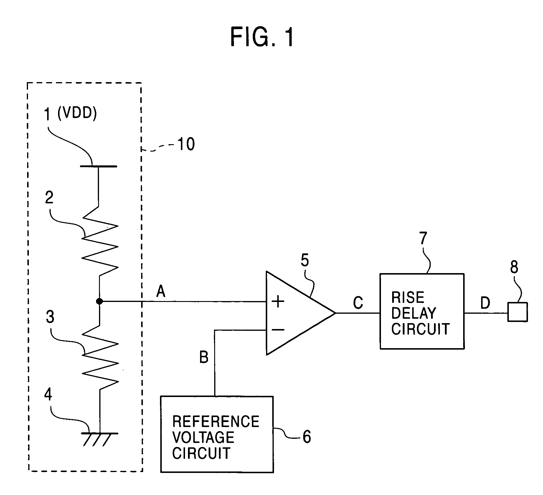
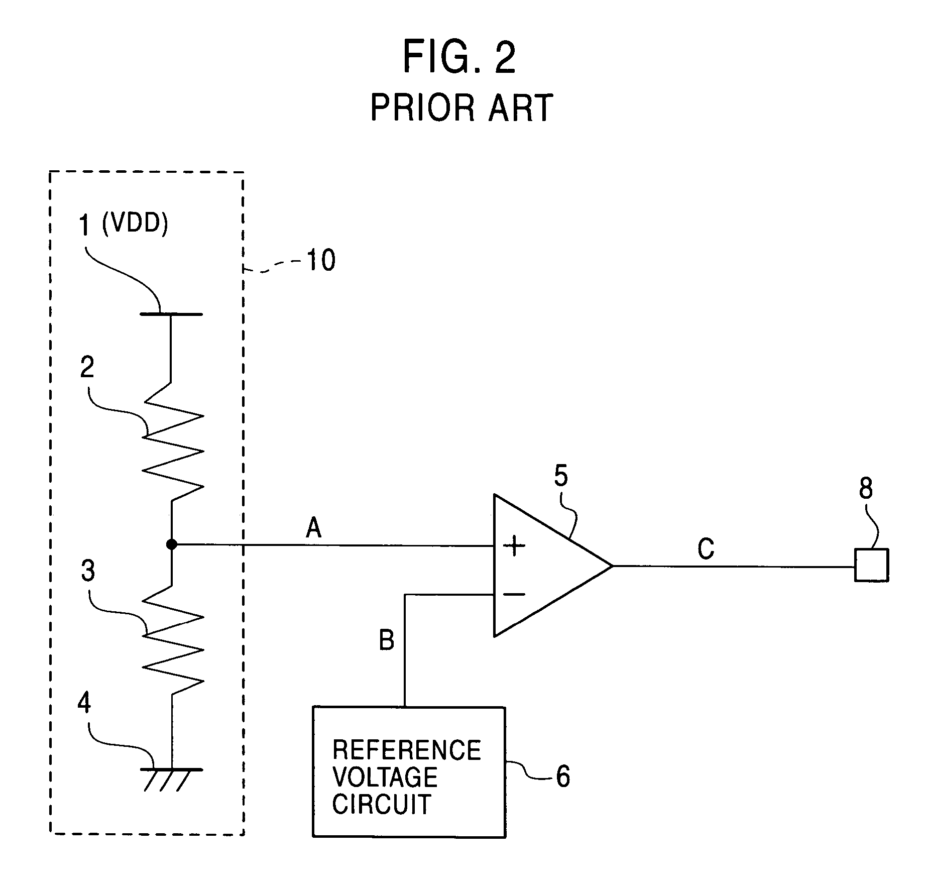
[0039]The voltage division circuit 10, the reference voltage circuit 6, and the comparator circuit 5 in the reset circuit according to the first embodiment operate in the same manner as those of the conventional reset circuit shown in FIG. 2 (see FIGS. 3 and 4).

[0040]In the reset circuit according to the first embodiment, the output signal C of the comparator circuit 5 is not directly used as a reset signal, and, instead, the signal D, obtained by delaying the rise of the output signal C through the rise delay circuit 7, is output as a reset signal at the “L” level. Specifically, the rise delay circuit 7 outputs a specific delay interval of the “L” level when the power supply voltage rises, and outputs a signal following the input signal C of the rise delay circuit 7 after the specific delay interval.

[004...

second embodiment

(B-3) Advantage of Second Embodiment

[0066]Even when the power supply voltage momentarily falls below the predetermined voltage V0 due to noise or the like and thus the comparator circuit output C falls to the “L” level, the reset circuit according to the second embodiment outputs no reset signal as described above, thereby preventing the system from operating abnormally due to frequent erroneous resets.

(C) Third Embodiment

[0067]A reset circuit according to a third embodiment of the present invention will now be described in detail with reference to the drawings.

(C-1) Configuration of Third Embodiment

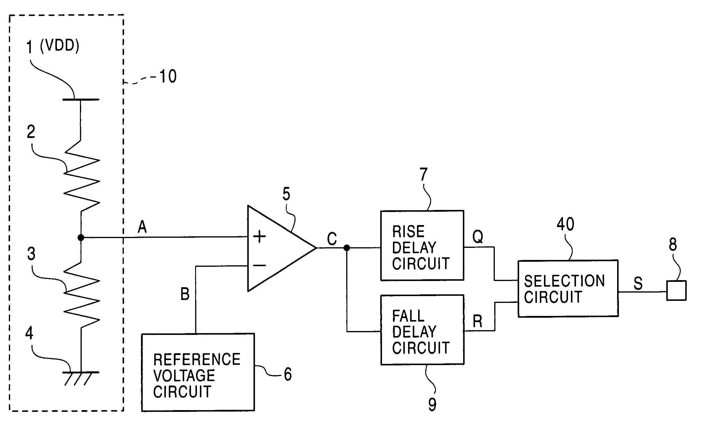
[0068]FIG. 12 is a block diagram illustrating a reset circuit according to the third embodiment, where elements identical or corresponding to those of the first and second embodiments shown in FIGS. 1 and 8 are denoted by the same reference numerals.

[0069]In FIG. 12, the reset circuit according to the third embodiment comprises a reset circuit body including a voltage division circuit 10...

third embodiment

(C-3) Advantage of Third Embodiment

[0084]As described above, the reset circuit according to the third embodiment selects, as its output signal, the output from the rise delay circuit 7 when the power supply voltage rises and the output from the fall delay circuit 9 when the reset circuit is in a reset release state, thereby providing a reset circuit which can output a proper reset signal even when the power supply voltage rises sharply and can also prevent output of a reset signal when the power supply voltage momentarily falls below the predetermined voltage V0 due to noise or the like.

(D) Other Embodiments

[0085]The rise delay circuit 7 and the fall delay circuit 9 may share some components although they are illustrated as completely separate circuits in the third embodiment. For example, the rise delay circuit 7 and the fall delay circuit 9 may be designed to share the inverters 21, 23, 25, and 26 and the capacitors 22 and 24 shown in FIG. 5, or the inverters 31, 33, 35, and 36 an...


PUM


Abstract

A circuit includes a reset circuit body and a delay circuit. The circuit body outputs a signal which indicates a reset when the supply of a supply voltage is initiated until the supply voltage reaches a sufficient value and indicates release of the reset after it reaches the sufficient value. The delay circuit outputs a signal obtained by delaying start of the indication of the release of the reset, taking into consideration of a sharp rise of the supply voltage. The reset circuit may include a circuit for eliminating a momentary change indicating the reset, and a selection circuit for selecting either an output of the delay circuit or an output of the momentary reset indication elimination circuit.

Description

BACKGROUND OF THE INVENTION[0001]1. Field of the Invention[0002]The present invention relates to a reset circuit for generating a reset signal which is provided to an electronic circuit or the like when power supply is initiated.[0003]2. Description of the Related Art[0004]A conventional reset circuit is described, for example, in Japanese Patent Publication Kokai No. 2002-228690. The conventional reset circuit will now be described with reference to FIG. 2.[0005]Referring to FIG. 2, the conventional reset circuit includes a voltage division circuit 10, a reference voltage circuit 6, a comparator circuit 5, and an output terminal 8. The voltage division circuit 10 linearly divides a power supply voltage VDD through two resistors 2 and 3, which are connected in series between a power supply terminal 1 and a ground terminal 4, and outputs a signal having a voltage A at the division point. The reference voltage circuit 6 outputs a signal having a reference voltage B. The comparator cir...

Claims


Application Information

Patent Timeline
Patent Type & Authority Patents(United States)
IPC IPC(8): H03L7/00
CPCH03K17/22H03K17/16
Inventor OHTAKE, HISAO
Owner LAPIS SEMICON CO LTD
Why Eureka
Try Eureka