Proximity probe transmitter

a technology of proximity probe and transmitter, which is applied in the direction of vibration measurement in solids, instruments, and stray field compensation, etc., can solve the problems of reducing the accuracy of the system, reducing the cost of preventive maintenance and repair, and reducing the power consumption requirements of the machinery. , the effect of minimizing the downtime of the machinery

Active Publication Date: 2008-03-06
METRIX INSTR
View PDF3 Cites 27 Cited by
  • Summary
  • Abstract
  • Description
  • Claims
  • Application Information

AI Technical Summary

Benefits of technology

[0019]In this regard, during operation, rather than trying to match resonant frequencies on-the-fly, the oscillator of the system is simply driven at a resonant frequency of the system determined upon start up of the transmitter once the system has been installed for operation. This not only removes the need for a phase locked loop but also eliminates the power consumption requirements of a phase locked loop circuit, and thus, the amount of power that is required for the overall monitoring system.
[0020]The transmitter of the invention also has the ability to be programmed in the field utilizing the appropriate calibration equipment. None of the vibration monitoring equipment of the prior art are field programmable primarily because they all utilize a standard linearization table that does not take into account differences among individual systems and configurations. This is especially true of prior art analog systems primarily because they are not programmable at all—each system has specific physical circuitry and boards designed for a specific operating parameter. Programmability will allow a user to reconfigure units to any set of parameters as needed. In other words, if a probe or cable is changed out, the system can be re-programmed to download a linearization table customized to the re-configured system. This will be a huge benefit for those who desire to minimize their machinery down time and improve their system accuracy. The calibration equipment can be a replicate of the system to calibrate units in house with maximum accuracy or it can be a simple software download to change the parameters of the transmitter with reduced accuracy.

Problems solved by technology

Over time, such machinery is subject to wear and potential failure.
Given the high operating RPM and high power dissipation of many industrial applications of such machinery, failure during operation may have severe consequences in terms of damage to the failed equipment itself as well as neighboring equipment and areas of the installation.
In addition, preventive machinery shut downs for maintenance and repair can be very costly in terms of facility downtime and direct expense in labor and replacement parts.
Preferably, such condition monitoring equipment can indicate when a piece of machinery is excessively worn or is otherwise operating improperly.
This can be inconvenient for automated target monitoring because depending on the region of the impedance vs. distance curve the system is operating at, small changes in impedance may indicate much larger changes in distance, or alternatively, large impedance changes may indicate small distance changes.
Two wire eddy current probe position monitoring devices typically have the disadvantage that the power available is limited by the minimum supply voltage and the minimum current consumption.
One drawback to analog eddy current proximity probes systems of the prior art is that such systems require a complex circuit which is difficult to manufacture and tune, and has an accuracy which is difficult to maintain.
More specifically, instrumentation personnel are faced with issues such as transmitter consistency when replacing a broken unit, dependable response over temperature and the need to sometimes maintain several versions of the transmitters for different machines.
These circuits are also prone to performance problems due to component variations.
This required much time and effort.
Prior art circuits were also prone to more drift over temperature which required additional circuitry to compensate for these drifts.
This generally limited the temperature range of the transmitter.
A drawback to PLL systems of the prior art is that these two wire devices typically consume a proportionally large amount of power.
Typically, vibration monitoring systems are limited by the minimum supply voltage and the minimum current consumption.
Phase locked loop circuits can draw as much as 5 to 7 mW which is undesirable in cases where there is a maximum current consumption limitation.

Method used


Image

  • Proximity probe transmitter
  • Proximity probe transmitter
  • Proximity probe transmitter

Examples


Embodiment Construction

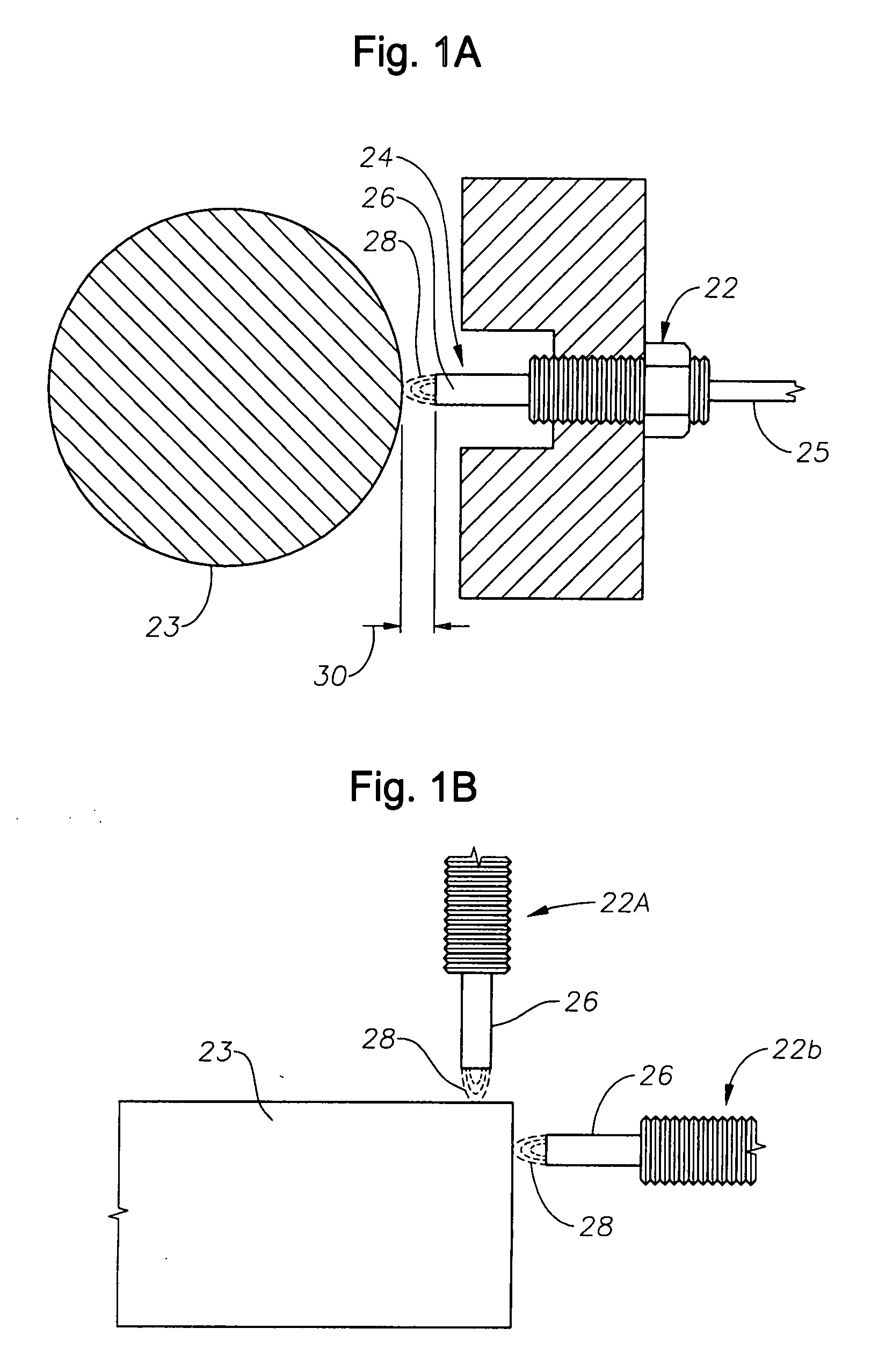
[0027]The principles of eddy current probe displacement monitoring is illustrated in FIGS. 1a and 1b. This Figures shows a cross sectional view of an eddy current probe 22 adjacent a target surface 23. At one end 24 of the probe 22 is a coil 26, preferably wound in a flat “pancake” configuration near the probe end 24. A coaxial cable 25 extends from the opposite end of probe 22. When coil 26 is excited with a radio frequency (RF) current, an electromagnetic field 28 penetrates the target surface 23. When the target 23 is conductive, this electromagnetic field induces eddy currents in the target material. These currents produce an additional electromagnetic field which affects the impedance of the coil 26. The magnitude of the eddy currents is dependent on the gap 30 between the probe tip 24 and the target surface 23, and therefore the impedance of the coil 26 is also dependent on the same gap. Measurements of the coil impedance (or, preferably, other parameters affected by coil impe...


PUM


Abstract

A digital based two wire proximity transmitter system and a method for calibrating the system, wherein the transmitter includes a customized linearization table uniquely generated during calibration to take into account the unique impedance properties of a particular probe/coaxial cable configuration. During calibration, the probe is positioned adjacent a calibration target. The calibration target is selected to have the same material characteristics as the target to be monitored during actual operation of the transmitter in the field. At a fixed distance between the probe and calibration target, the resonant frequency of the probe/cable system is determined. Thereafter, utilizing this resonant frequency to excite the probe, the voltage response of the probe/cable system is determined as the distance between the probe and the target material is incrementally changed. The voltage output is used to build a table for incremental distances, wherein each distance is characterized by a non-linear output that has been equated to a linear output. This uniquely generated table is subsequently downloaded into the transmitter for reference during monitoring.

Description

BACKGROUND OF THE INVENTION[0001]1. Field of the Invention[0002]The present invention relates to vibration monitoring equipment and more specifically to proximity probe sensors used to monitor vibrations in motors and shafts and to identify excessive vibrations therein.[0003]2. Prior Art[0004]Rotating machinery such as motors, generators, and turbines find widespread application in areas such as manufacturing, power generation, materials processing, as well as many others. Over time, such machinery is subject to wear and potential failure. Given the high operating RPM and high power dissipation of many industrial applications of such machinery, failure during operation may have severe consequences in terms of damage to the failed equipment itself as well as neighboring equipment and areas of the installation. In addition, preventive machinery shut downs for maintenance and repair can be very costly in terms of facility downtime and direct expense in labor and replacement parts.[0005...

Claims


Application Information

Patent Timeline
Patent Type & Authority Applications(United States)
IPC IPC(8): G01B7/14
CPCG01B7/023G01H1/08G01H1/06
Inventor DOBSKY, DAVID
Owner METRIX INSTR
Why Eureka
Try Eureka