
Starting device and starting method for a single-phase induction motor

a single-phase induction motor and starting device technology, applied in the direction of single-phase induction motor starters, electric/dynamo-electric converter control, electric/dynamo-electric converter starters, etc., can solve the problems of generating electromagnetic and other noise, unable to use the electric motor in high-efficiency motors, and presenting electrical mechanical relays, so as to reduce the susceptibility to load variation and the effect of accelerating the disassembly of the starting coil

Inactive Publication Date: 2006-12-07
EMBRACO IND DE COMPRESSORES E SOLUCOES EM REFRIGERACAO LTDA
View PDF11 Cites 10 Cited by
  • Summary
  • Abstract
  • Description
  • Claims
  • Application Information

AI Technical Summary

Benefits of technology

[0011] Thus, it is an object of the present invention to provide a starting device having a simple, strong and low cost construction, which permits: large scale usage in low cost systems, presenting the advantages of the timed devices in which the residual power consumption is eliminated; reducing the number of components so as to comply with a determined family of motors having the same supply voltage; the use in high efficiency motors with running capacitors; and which presents the characteristic of the electromechanical relays, in which the starting time is optimized for each electric motor size.
[0014] It is a further object of the present invention to provide a starting electronic device for a single phase induction motor with negligible energy consumption.
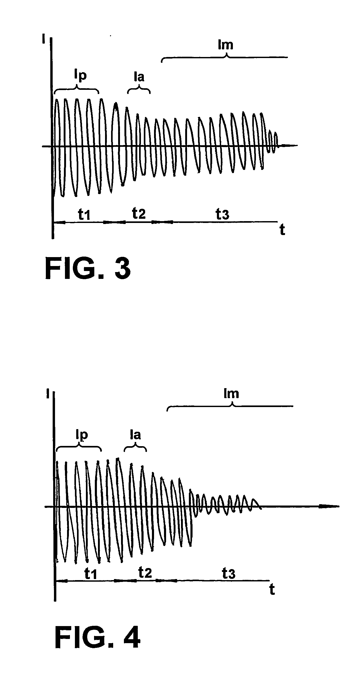
[0023] Since the current is recorded in each starting period, the starting device is sensitive to the different torque levels required during the starting process, so that load variations in the motor shaft which can extend the starting period will maintain the energization in the starting coil during a period long enough to overcome the restrictions imposed to the electric motor. On the other hand, in a situation where the load condition imposed to the motor during said period is reduced, the rotor acceleration will occur in a shorter period, promoting a more accentuated reduction in the current levels consumed by the electric motor, so that the device can disable the starting coil more rapidly.

Problems solved by technology

On the other hand, the electromechanical relay presents several limitations, especially the need of dimensioning a specific component for each size of electric motor, the impossibility of using it in high efficiency motors in which a running capacitor is used, generation of electromagnetic and other noises during operation of the motor and wear of its components caused by electric arc and mechanical friction.
Since its operation is based on heating a ceramic tablet, increasing its electrical resistance and consequently limiting the circulating current, there occurs dissipation of residual power during all its operating time.
Another limitation of this component is related to the time interval required to allow consecutive starts to occur.
Its conduction time is directly proportional to the volume of the ceramic tablet and inversely proportional to the circulating current, resulting in a reduced starting time when applied to high power motors, and in an excessively long time when applied to smaller motors.
These two facts lead to a deficiency in the start of the larger motors and to higher energy consumption during the starting period of the smaller motors.
On the other hand, the timed starting components eliminate the great disadvantage of the PTC residual consumption, but do not overcome the deficiency in the starting time required for the different motor sizes.

Method used


Image

  • Starting device and starting method for a single-phase induction motor
  • Starting device and starting method for a single-phase induction motor
  • Starting device and starting method for a single-phase induction motor

Examples


Embodiment Construction

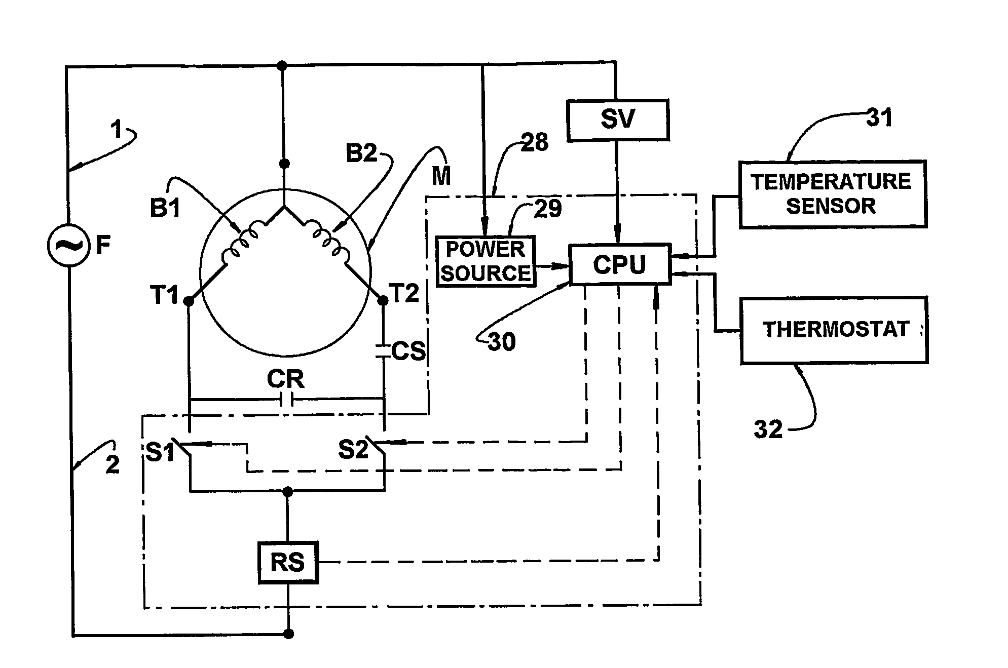
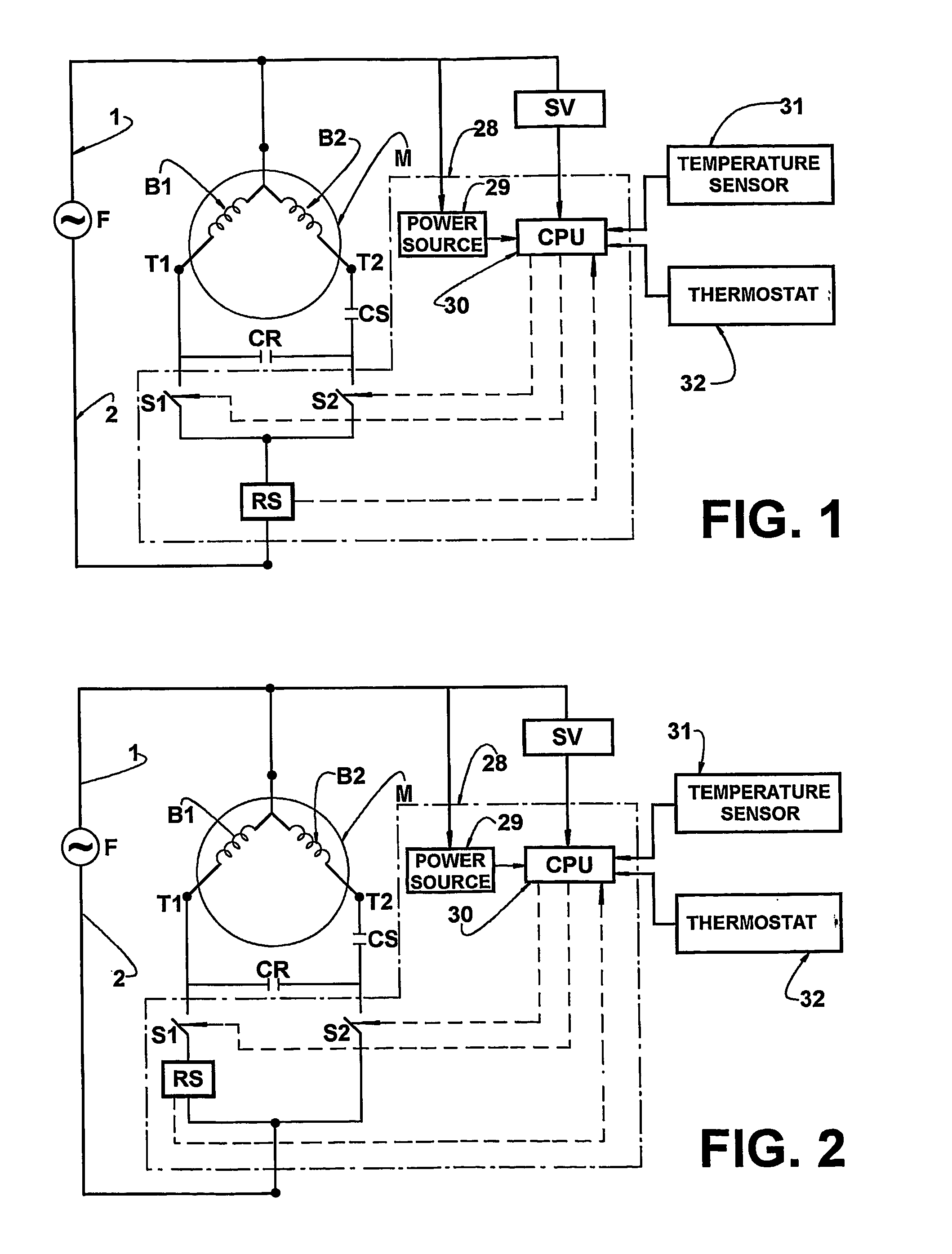
[0031] The starting device for a single phase induction motor of the present invention will be described for a motor comprising: a stator B having a running coil B1 and a starting coil B2; a power source F, which supplies current to both the running coil B1 and the starting coil B2; a running switch S1 and a starting switch S2, respectively connecting the running coil B1 and the starting coil B2 to the power source F when in a closed condition, said starting switch S2 being conducted to an open condition upon completion of the motor start, said starting device comprising a starting circuit 10 including, besides the running switch S1 and the starting switch S2: a current sensor RS connected in series between the power source F and the stator B, in order to detect the current level supplied to the latter; and a control unit 11 supplied by the power source F and receiving, from the current sensor RS, signals representative of the current level being supplied to the stator B and, from a...


PUM


Abstract

A starting device and starting method for a single-phase induction motor, comprising: a stator (B) having a running coil (B1) and a starting coil (B2); a running switch (S1) and a starting switch (S2) which is conducted to an open condition upon completion of the motor start. The starting device comprises: a starting circuit (10) including a control unit (11) which receives, from a current sensor (RS), signals representative of the current level being supplied to the stator (B), said control unit (11) being connected to the running and the starting switches (S1 and S2), for instructing the open and closed conditions thereof, the open condition of the starting switch (S2) being defined when the ratio (K) between the present current level (Ia) supplied to the stator (B) and the starting current level (Ip), upon the closing of the starting and the running switches (S1 and S2), reaches a predetermined value (Km).

Description

FIELD OF THE INVENTION [0001] The present invention refers to an electronic starting device of the type used in electric motors, particularly in single-phase induction motors. BACKGROUND OF THE INVENTION [0002] Single-phase induction motors are widely used, due to their simplicity, strength and high performance. They are generally found in household appliances, such as refrigerators, freezers, air conditioners, hermetic compressors, laundry machines, pumps, fans, and in some industrial applications. [0003] The known induction motors are usually provided with a cage type rotor and a coiled stator having two windings, one for the running coil and the other for the starting coil. During the normal operation of the compressor, the running coil is supplied by an AC voltage and the starting coil is temporarily supplied at the beginning of the starting operation, creating a turning magnetic field in the air gap of the stator, a necessary condition to accelerate the rotor and start the moto...

Claims


Application Information

Patent Timeline
Patent Type & Authority Applications(United States)
IPC IPC(8): H02P1/42H02P1/44
CPCH02P1/44H02P1/42
Inventor DUARTE, RONALDO RIBERIOSCHWARZ, MARCOS GUILHERMEMEDEIROS NETO, LUIZ MAGALHAES
Owner EMBRACO IND DE COMPRESSORES E SOLUCOES EM REFRIGERACAO LTDA
Learn More