Capacitor discharging circuit and power converter

a technology of capacitor and discharging circuit, which is applied in the direction of electric power, electric vehicles, transportation and packaging, etc., can solve the problems of increasing power loss, reducing the efficiency of electrical equipment, and increasing so as to reduce and eliminate the power consumption of discharging resistors

Active Publication Date: 2015-02-10
DELTA ELECTRONICS (SHANGHAI) CO LTD
View PDF5 Cites 10 Cited by
  • Summary
  • Abstract
  • Description
  • Claims
  • Application Information

AI Technical Summary

Benefits of technology

[0015]In view of the severe power loss caused by a discharging resistor which the previous solution requires, the present application, in part, seeks to avoid the power consumption of discharging resistor when AC power is introduced, and proposes a solution to discharge X-capacitor through an energy consumption unit when AC power is off, without using the discharging resistor.
[0018]As can be seen from the technical resolution stated above, the characteristic of the capacitor discharging device provided by the present application is that the X-capacitor between live line and null line of AC power input terminal of the converter is discharged by an energy consumption unit, not by a discharging resistor. That is to say, when AC power is introduced normally, the AC power-off signal outputted from the AC power-off detecting unit is unable to affect the control unit; the control unit accomplishes the design function of the power converter on the basis of the original design method. With no discharging resistor connected between the two terminals of the X-capacitor, the power consumption of the discharging resistor is eliminated. When AC power is disconnected, the control unit affected by the AC power-off detecting unit controls the operation of the energy consumption unit to consume the energy stored in the capacitor. In this way, the present application enhances the efficiency of electrical equipment, which meets the requirement of “safety of information technology equipment”.
[0019]In addition, the device in the original conversion unit can be used as the energy consumption unit, which reduces the power consumption of the discharging resistor and enhances efficiency in the light-load mode, and simplifies the circuit at the same time. Meanwhile, for the two-stage conversion module, high efficiency in the heavy-load mode can be achieved when a bridgeless PFC conversion unit being used. And low efficiency in the light-load mode is obtained when a discharging resistor being used if the X-capacitor is with large capacitance. The method of the present invention can effectively enhance the efficiency of the power converter including a bridgeless PFC conversion unit.

Problems solved by technology

Specifically positioned, X-capacitor will be charged upon the introduction of AC power, and will store energy in power plug when AC power is disconnected, which is likely to induce current leakage or make the enclosure charged to endanger user safety.
However, the discharging resistor 3 will consume energy all along and induce power loss, especially, the power loss will become greater when the input voltage being higher, which is an important factor leading to the power loss of the converter during standby mode and no-load mode.
The lower the resistance is, the greater the power loss of the discharging resistor is when AC power is introduced, which could lead to lower efficiency of the bridgeless PFC conversion unit in the light-load mode.

Method used


Image

  • Capacitor discharging circuit and power converter
  • Capacitor discharging circuit and power converter
  • Capacitor discharging circuit and power converter

Examples


Embodiment Construction

[0040]Some exemplary embodiments explaining the features and advantages of the present invention will be stated in detail in the following description. It is to be understood that different embodiments of the present invention have a variety of variations, which will fall within the scope of the present invention, and the description and figure showing are essentially used to explain the present invention, but not to limit the present invention.

[0041]The features and beneficial effects mentioned above, as well as other features and effects will be described in detail with embodiments of the X-capacitor discharging device of the present invention in conjunction with the attached FIG. 2-19.

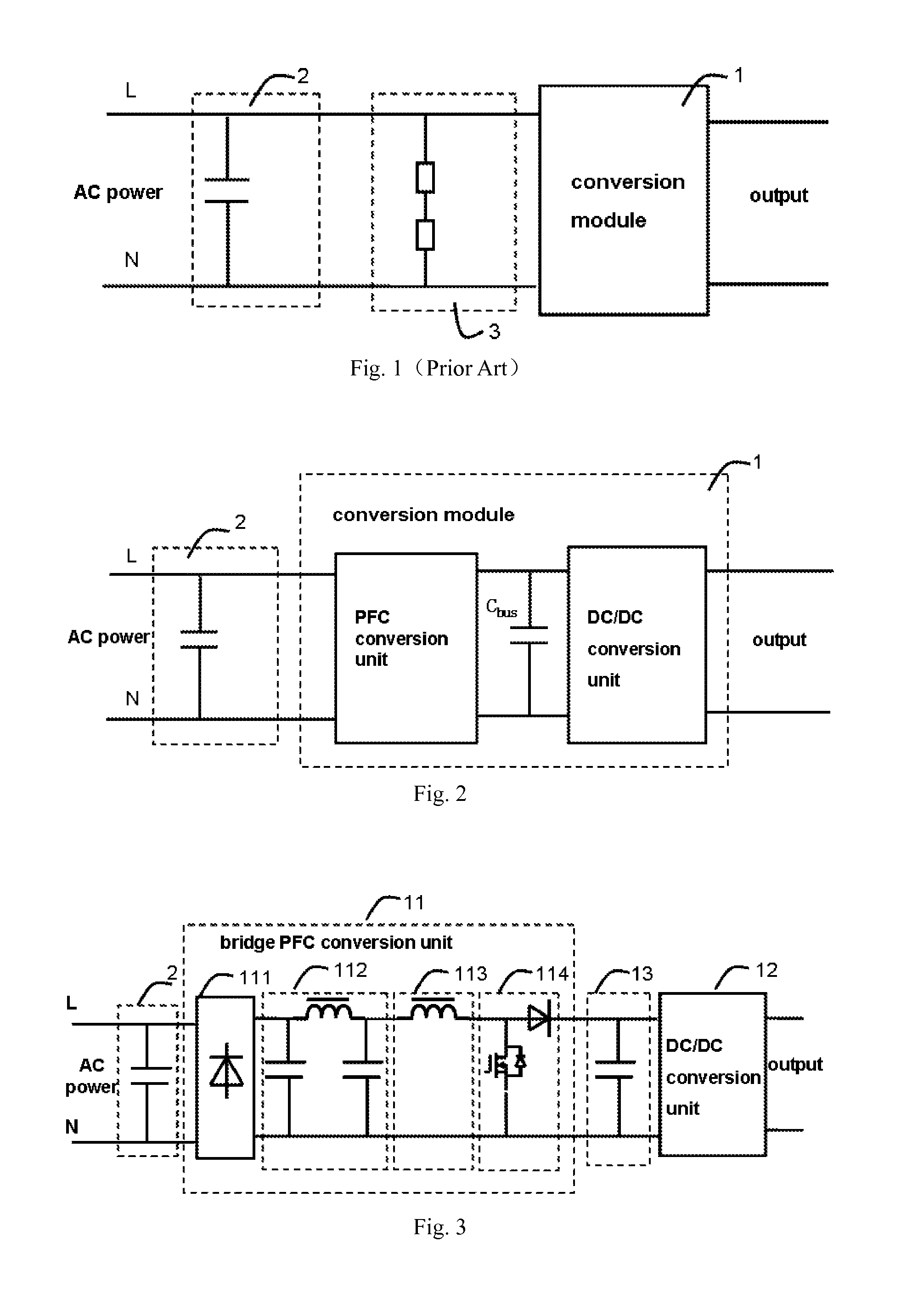
[0042]As shown in FIG. 2, an AC-DC power converter (e.g. power adapter) or an AC-AC power converter, having AC power input terminals and output terminals, usually includes a capacitor 2 (usually called X-capacitor) connected between live line and null line of AC power input terminals, and a conversi...


PUM


Abstract

A capacitor discharging circuit and a power converter having the capacitor discharging circuit are disclosed. The capacitor discharging circuit comprises a conversion module connected with the two terminals of the capacitor, an AC power-off detecting unit used to detect on-off state of AC power, and a control unit. The conversion module comprises an energy consumption unit. When AC power is disconnected, the AC power-off signal generated by the AC power-off detecting unit intervenes the control unit to control the energy consumption unit to consume the energy stored in the capacitor.

Description

CROSS REFERENCE TO RELATED APPLICATIONS[0001]This application claims priority to the Chinese patent application No. 201210019923.2, filed Jan. 20, 2012, which is incorporated herein by reference in its entirety.FIELD OF THE INVENTION[0002]The present invention generally relates to a discharging device used in the field of power electronic technology, and more particularly to a capacitor discharging circuit and a power converter with the capacitor discharging circuit.BACKGROUND OF THE INVENTION[0003]Under normal circumstance, in order to meet the requirement of electromagnetic compatibility, a filter configuration comprising a capacitor is connected between AC power and the electronic devices. In compliance with the “safety of information technology equipment” standard, the capacitor is a safety capacitor which comprises X-capacitors and Y-capacitors. X-capacitor is connected between L line (Live line) and N line (Null line) of the input terminals of AC power.[0004]Specifically posit...

Claims


Application Information

Patent Timeline
Patent Type & Authority Patents(United States)
IPC IPC(8): H02M1/00
CPCH02M1/32H02M7/217H02M1/322
Inventor JIN, HONGYUANWANG, BAOCHENGAN, HONGJIANYING, JIANPING
Owner DELTA ELECTRONICS (SHANGHAI) CO LTD
Why Eureka
Try Eureka