Gauge tee device

a tee device and gauging technology, applied in the direction of fluid pressure measurement, branching pipes, instruments, etc., can solve the problems of limited use of disposable devices, low flow rate and small tubing sizes, and inability to reliably and low cost systems developed for disposable us

Active Publication Date: 2008-05-20
MEISSNER FILTRATION PRODS
View PDF9 Cites 14 Cited by
  • Summary
  • Abstract
  • Description
  • Claims
  • Application Information

AI Technical Summary

Benefits of technology

[0014]The present invention provides a disposable sanitary gauge tee with no “dead zone” for use in pressure measurement of fluid in disposable tubing including a body having a main fluid passageway in fluid connection with a proximal end of a pressure fluid passageway, the main fluid passageway including a fluid port and a second fluid port, wherein a hose barb is operatively attached to the body at the fluid port and the second fluid port, wherein the disposable tubing can be removably attached to the hose barbs, and the pressure fluid passageway including a distal end for removable attachment of a sanitary pressure gauge and a biocompatible gauge protector for isolation of the fluid from the sanitary pressure gauge. To achieve the no dead zone, the proximal end of the pressure fluid passageway is substantially the same diameter as the distal end of the pressure fluid passageway, therein providing a total transfer of fluid within the pressure fluid passageway during fluid flow.

Problems solved by technology

While methods for obtaining such information have existed for a long time, no reliable low cost systems have been developed for disposable use.
However, this device can only be used with low flow rates and small tubing sizes.
Further, the device requires a computer or electronic interface for the pressure readout.
In general, disposable pressure sensors that are provided pre-sterilized have limitations in that they cannot be calibrated before their use.
This is a key drawback to use in the biopharmaceutical industry because calibration prior to the use of pressure gauges is required during Good Manufacturing Practices (GMP) production.
As a result, contamination of the gauge tee can occur.
Furthermore, considerable hold-up volume results (5-50 mL).
However, such a device could not be used readily in a biopharmaceutical process, as the gauge must be calibrated before and after use.
Meeting GMP processing standards is required for processing biopharmaceuticals, and calibrating a gauge after use will jeopardize the batch processed if the calibration fails.
Again, this device requires a gauge that must be calibrated before and after use, and thus could not be used in biopharmaceutical processes.
Such a device could not be used in biopharmaceutical processes because the fluid is in contact with the gauge itself, allowing for contamination.

Method used


Image

  • Gauge tee device
  • Gauge tee device
  • Gauge tee device

Examples


first embodiment

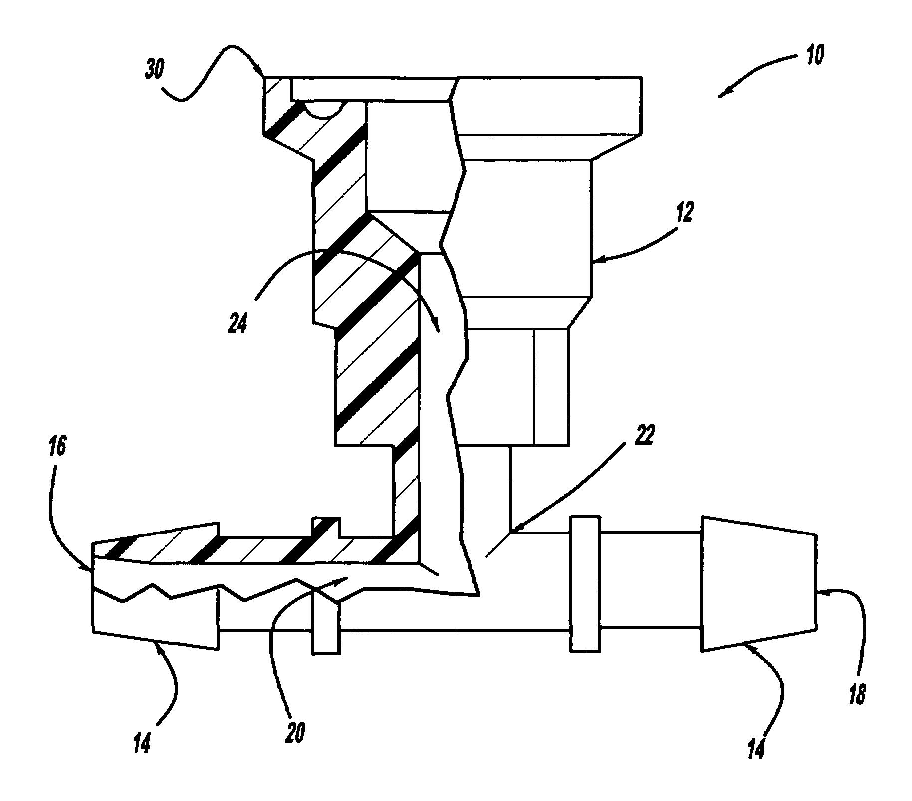
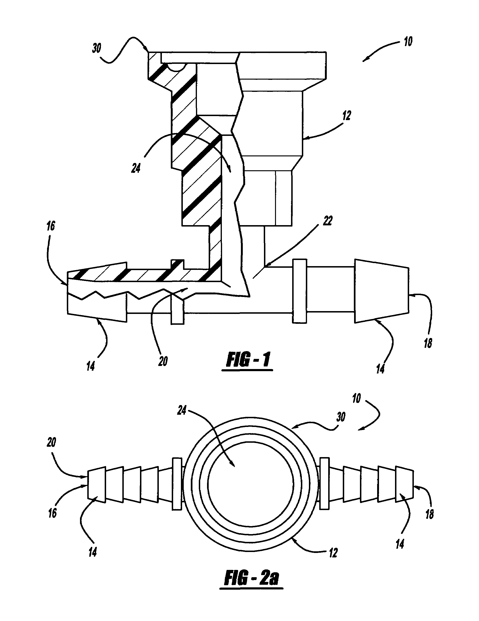
[0035]The present invention has numerous advantages over the prior art. There are very few other ways to measure pressure in disposable tubing other than pressure sensors with attached hose barbs and a digital readout. The present invention provides minimal hold-up volume by utilizing a cup-like design of the pressure fluid passageway, as described below. It can be used in disposable filtration systems for biopharmaceuticals or other liquids. For example, the present invention allows for accurate pressure monitoring of liquids in disposable tubing during bioprocess filtration, chromatography, or other pressure controlled processes. Since the gauge tee device 10 of the present invention can be sterilized, it can be utilized for disposable tubing and bag systems and allows for aseptic pressure monitoring of a process. The gauge tee device 10 of the present invention is disposable, which eliminates the need for cleaning or cleaning validation since it is used only one time (a great ben...

second embodiment

[0042]the gauge tee device 10′ is shown in FIGS. 6 and 7 of a ¾ inch disposable sanitary gauge tee including compression fittings 40′ that can accommodate ¼ inch inner diameter or ⅜ inch inner diameter disposable tubing 32. This gauge tee device 10′ allows pressure to be monitored during fluid processing in disposable tubing. Further, the compression fitting 40′ allows for use in systems and / or processes that exert greater than 15 psid. The gauge tee device 10′ includes a sanitary gauge tee body 12′ in operative connection with compression fittings 14′. A first fluid port 16′ is in fluid connection with a second fluid port 18′ at each compression fitting 14′ through a main fluid passageway 20′. The main fluid passageway 20′ is also in fluid connection with a proximal end 22′ of a pressure fluid passageway 24′. A biocompatible gauge protector 26 and a sanitary pressure gauge 28 can be removably attached to a distal end 30′ of the pressure fluid passageway 24′ in order to measure the ...

third embodiment

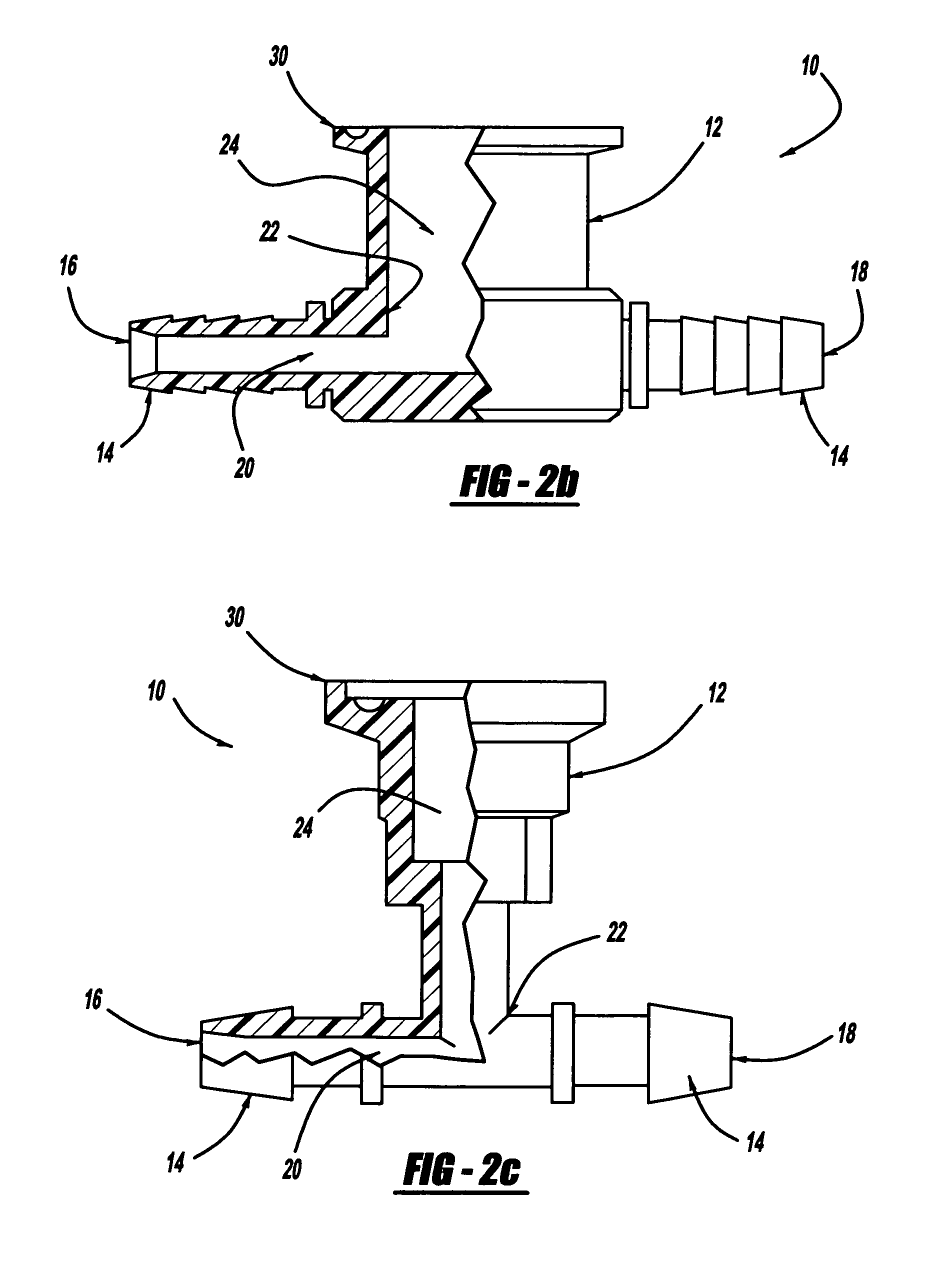
[0044]In use, the gauge tee device 10, 10′, 10″ can be hooked up to a line of tubing 32 in order to measure the pressure of the fluid within that line. The tubing 32 is attached at the hose barbs 14, 14′, 14″ and can be secured by the securing device 34 or compression fittings 40′. The biocompatible gauge protector 26 is placed over the distal end 30, 30′, 30″ of the pressure fluid passageway 24, 24′, 24″ to protect the fluid from the metal of the sanitary pressure gauge 28. The sanitary pressure gauge 28 is next attached to the 30, 30′, 30″ of the pressure fluid passageway 24, 24′, 24″ and can be secured by the sanitary clamp 38. Fluid is then flowed through the tubing 32 and the pressure of the fluid is monitored by the sanitary pressure gauge 28. Fluid flowing up the pressure fluid passageway 24″ in the third embodiment also flows completely out because of the cup-like design, ensuring that no fluid remains to contaminate the process.

[0045]In another embodiment of the present inv...


PUM

PropertyMeasurementUnit
volumeaaaaaaaaaa
lengthaaaaaaaaaa
heightaaaaaaaaaa

Abstract

A disposable sanitary gauge tee with no dead zone for use in pressure measurement of fluid in disposable tubing including a body having a main fluid passageway in fluid connection with a proximal end of a pressure fluid passageway, the main fluid passageway including a fluid port and a second fluid port, wherein a hose barb is operatively attached to the body at the fluid port and the second fluid port, wherein the disposable tubing can be removably attached to the hose barbs, and the pressure fluid passageway including a distal end for removable attachment of a sanitary pressure gauge and a biocompatible gauge protector for isolation of the fluid from the sanitary pressure gauge. No dead zone is achieved within the gauge tee as the proximal end of the pressure fluid passageway is substantially the same diameter as the distal end of the pressure fluid passageway, therein providing a total transfer of fluid within the pressure fluid passageway during fluid flow. A method of measuring pressure of fluid within disposable tubing using the disposable sanitary gauge tee and a method of measuring pressure of fluid in a closed system are further included.

Description

CROSS-REFERENCE TO RELATED APPLICATIONS[0001]This application claims the benefit of priority under 35 U.S.C. Section 119(e) of U.S. Provisional Patent Application No. 60 / 683,091, filed May 20, 2005, which is incorporated herein by reference.BACKGROUND OF THE INVENTION[0002]1. Technical Field[0003]The present invention relates to the field of tubing and filtration devices and more specifically towards gauges.[0004]2. Background Art[0005]Currently, various devices exist for measuring pressure within disposable tubing because it can be very beneficial to obtain and monitor relevant flow characteristics of fluids passing through the tubing. While methods for obtaining such information have existed for a long time, no reliable low cost systems have been developed for disposable use.[0006]One prior art device for measuring pressure within tubing utilizes disposable pressure sensors with a luer lock fitting, as in U.S. Pat. No. 4,576,181. However, this device can only be used with low flow...

Claims


Application Information

Patent Timeline
Patent Type & Authority Patents(United States)
IPC IPC(8): G01L7/00
CPCF16L41/008F16L41/021
Inventor FENNINGTON, JR., GEORGE J
Owner MEISSNER FILTRATION PRODS
Why Eureka
Try Eureka