
Cold cathode fluorescent lamp driving system

a driving system and fluorescent lamp technology, applied in the direction of lighting apparatus, instruments, light sources, etc., can solve the problems of limited power required to generate light, one ccfl lamp may be ignited, and not all lamps may be completely ignited

Inactive Publication Date: 2008-05-20
GOLD CHARM LTD
View PDF7 Cites 0 Cited by
  • Summary
  • Abstract
  • Description
  • Claims
  • Application Information

AI Technical Summary

Benefits of technology

[0004]Fluorescent lamps are typically used in a number of applications where artificial light is required but the power required to generate the light is limited. One such application is the backlighting for a notebook computer or similar portable electronic device. One popular type of fluorescent lamp is the cold cathode fluorescent lamp (CCFL), which is almost universally used in the panels of various LCDs (liquid crystal displays). The CCFL requires a high starting voltage (on the order of 700-1,600 volts) for a short period of time, to ionize the gas contained within the lamp tube and thereby ignite the lamp. After the gas in the CCFL is ionized and the lamp is lit, less voltage is needed to keep the lamp on.

Problems solved by technology

Fluorescent lamps are typically used in a number of applications where artificial light is required but the power required to generate the light is limited.
One of the problems with the circuit shown in FIG. 3 is that one CCFL lamp may be ignited while the other one is still dormant.
That is, not all of the lamps may be completely ignited.
However, if either of the CCFL lamps is not ignited (i.e., stays dormant), the lighting of the entire large panel may be significantly affected.
Furthermore, the dormant lamp may degrade the expected working lifetime of the other lamp, because each of the lamps bears much more current than previously.

Method used


Image

  • Cold cathode fluorescent lamp driving system
  • Cold cathode fluorescent lamp driving system
  • Cold cathode fluorescent lamp driving system

Examples


Embodiment Construction

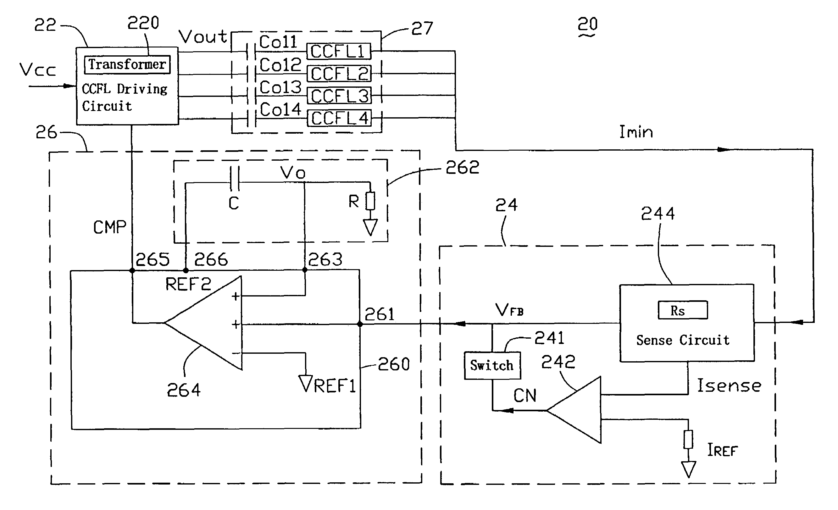
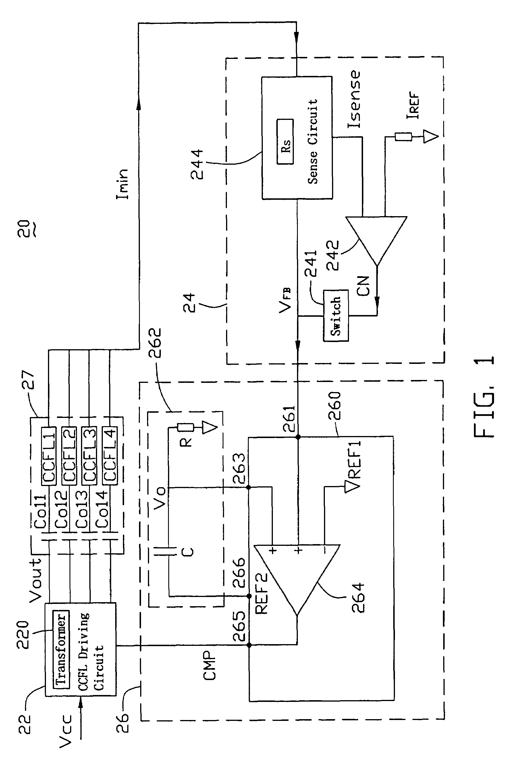
[0015]The CCFL driving system described hereinbelow is adaptable for multiple cold cathode fluorescent lamps (CCFLs). The CCFLs are arranged, for example, on a large panel or panels with a minimum of 6 in a group. There may also be other suitable arrangements for the CCFLs in various applications. The following description is of a driving system with only four lamps, for the purposes of exemplary illustration of embodiments of the present invention. The embodiments of the present invention are not to be limited by the number of loads, nor are they to be limited to CCFL loads or any other particular type of load.

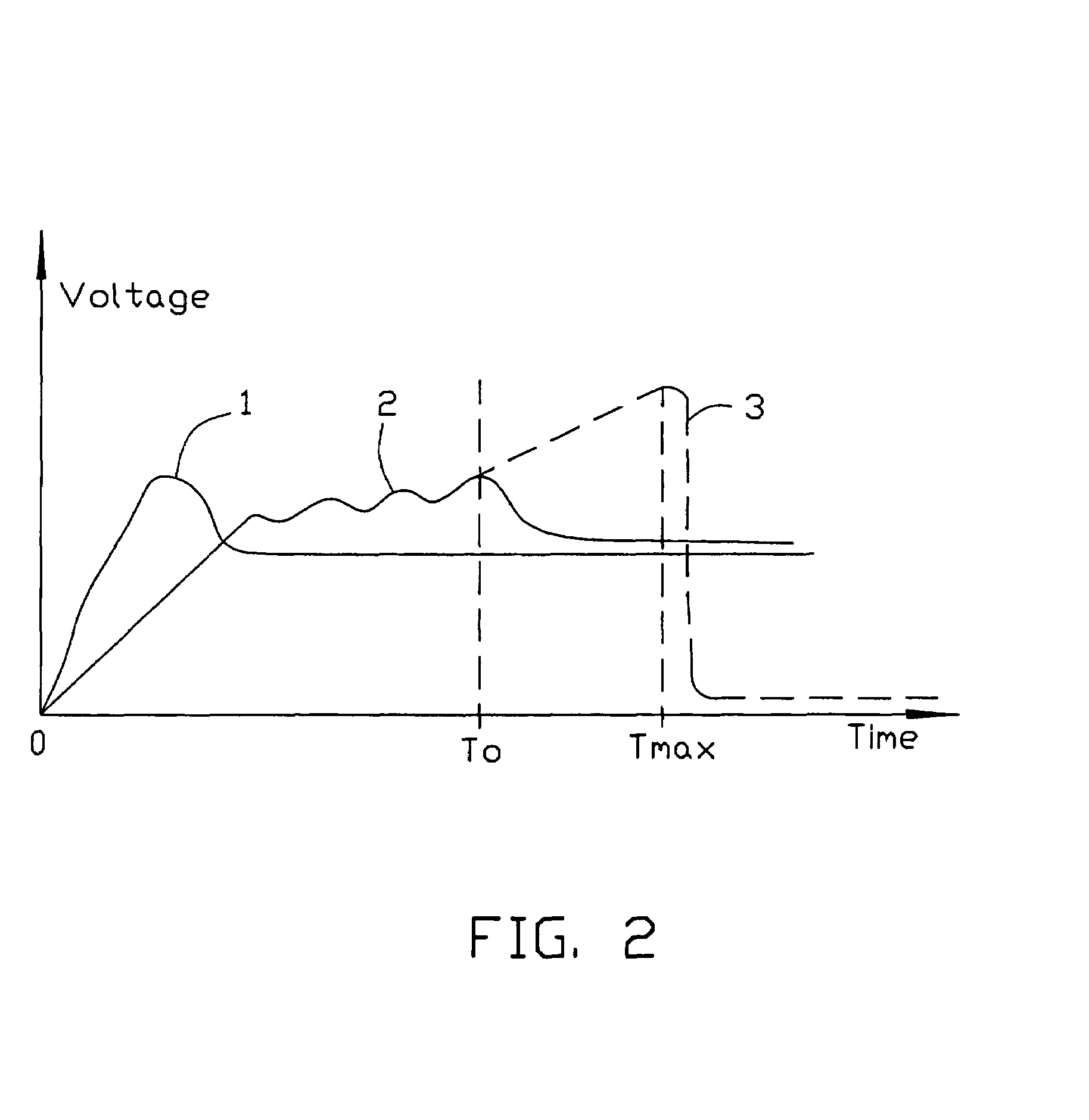
[0016]Referring to FIGS. 1 and 2, a CCFL driving system 20 for four CCFL loads according to a preferred embodiment of the present invention is shown. As a general overview, the present CCFL driving system 20 is operable to generate a predetermined voltage (shown in FIG. 2 as a voltage curve 2) during a warm-up stage, and then generate an appropriate pulse or pulse-like signal...


PUM


Abstract

A CCFL (cold-cathode fluorescent lamp) driving system for multiple CCFL loads includes a transformer, a CCFL circuit, and a controlling circuit coupled between the transformer and the CCFL circuit. The CCFL circuit includes multiple CCFL loads. The transformer includes a primary winding and a secondary winding, with the primary winding coupled to a voltage source and the secondary winding coupled to the CCFL loads. The controlling circuit includes a part for generating a predetermined voltage signal to power the CCFL loads during a warm-up stage and another part for generating a modulation signal. With such circuit arrangement, each of the multiple CCFL loads is powered from an off state to an operationally-on state.

Description

BACKGROUND OF THE INVENTION[0001]1. Field of the Invention[0002]The present invention relates to cold cathode fluorescent lamp (CCFL) driving systems for CCFL loads, and particularly to a driving system that powers on multiple CCFL loads from an off state to an operationally-on state.[0003]2. General Background[0004]Fluorescent lamps are typically used in a number of applications where artificial light is required but the power required to generate the light is limited. One such application is the backlighting for a notebook computer or similar portable electronic device. One popular type of fluorescent lamp is the cold cathode fluorescent lamp (CCFL), which is almost universally used in the panels of various LCDs (liquid crystal displays). The CCFL requires a high starting voltage (on the order of 700-1,600 volts) for a short period of time, to ionize the gas contained within the lamp tube and thereby ignite the lamp. After the gas in the CCFL is ionized and the lamp is lit, less v...

Claims


Application Information

Patent Timeline
Patent Type & Authority Patents(United States)
IPC IPC(8): H05B37/00
CPCH05B41/2822H05B41/382
Inventor HSIEH, KUAN-HONGCHUNG, SHIN-HONGBAO, WEI-DE
Owner GOLD CHARM LTD
Learn More