Dust collecting apparatus for vacuum cleaner

a technology for vacuum cleaners and dust collecting equipment, which is applied in cleaning equipment, filtration separation, separation processes, etc., can solve the problems of not being able to obtain a high suction force, not being able to obtain proper dust collection efficiency without a filter, and further lowering the suction force. achieve the effect of improving the efficiency of dust separation

Inactive Publication Date: 2008-06-03
SAMSUNG GWANGJU ELECTRONICS CO LTD
View PDF32 Cites 91 Cited by
  • Summary
  • Abstract
  • Description
  • Claims
  • Application Information

AI Technical Summary

Benefits of technology

[0010]The present disclosure has been developed in order to solve the above and other problems associated with the related art. A feature of the present disclosure is to provide a dust collecting apparatus which can improve a dust separating efficiency without a filter disposed between a dirt separating chamber in which dirt is separated primarily and a cyclone chamber in which fine dust is separated secondarily.
[0011]Another feature of the present disclosure is to provide a dust collecting apparatus which can prevent a back flow of the collected dirt and dust from the cyclone chamber.
[0012]Yet another feature of the present disclosure is to provide a dust collecting apparatus which can ensure visibility for observing the dust separating chamber and the cyclone chamber disposed in the dust collecting apparatus from the outside even during the operation of the vacuum cleaner without separating the dust collecting apparatus from the vacuum cleaner.
[0016]Preferably, the first and second dust separating chambers are isolated from each other by a partition wall, and at least a part of the partition wall is made of the transparent material so as to increase visibility.

Problems solved by technology

However, in the conventional dust collecting apparatus, since an air suction part of the first dust collecting chamber and an exhaust part of the second cyclone dust collecting chamber are positioned collinearly, there is a disadvantage that it can not be expected to obtain proper dust collecting efficiency without the filter.
Further, there is another problem in that the filter should be periodically cleaned so that the dust and dirt attached on the filter can be removed, since the dust and dirt is attached and accumulated on the filter.
Further, since the conventional dust collecting apparatus has a single cyclone chamber and thus has a suction and exhaust flow path having a narrow sectional area, it can not be expected to obtain a high suction force and it is also apparent that the suction force is further lowered when the filter is choked up with the dust and dirt.
Furthermore, in the conventional dust collecting apparatus, since the first and second dust collecting chambers are not visible from the outside, when the dirt drawn-in in the dust collecting apparatus has a large size, the user can not know where the large-sized dirt is caught in the collecting apparatus.

Method used


Image

  • Dust collecting apparatus for vacuum cleaner
  • Dust collecting apparatus for vacuum cleaner
  • Dust collecting apparatus for vacuum cleaner

Examples


first embodiment

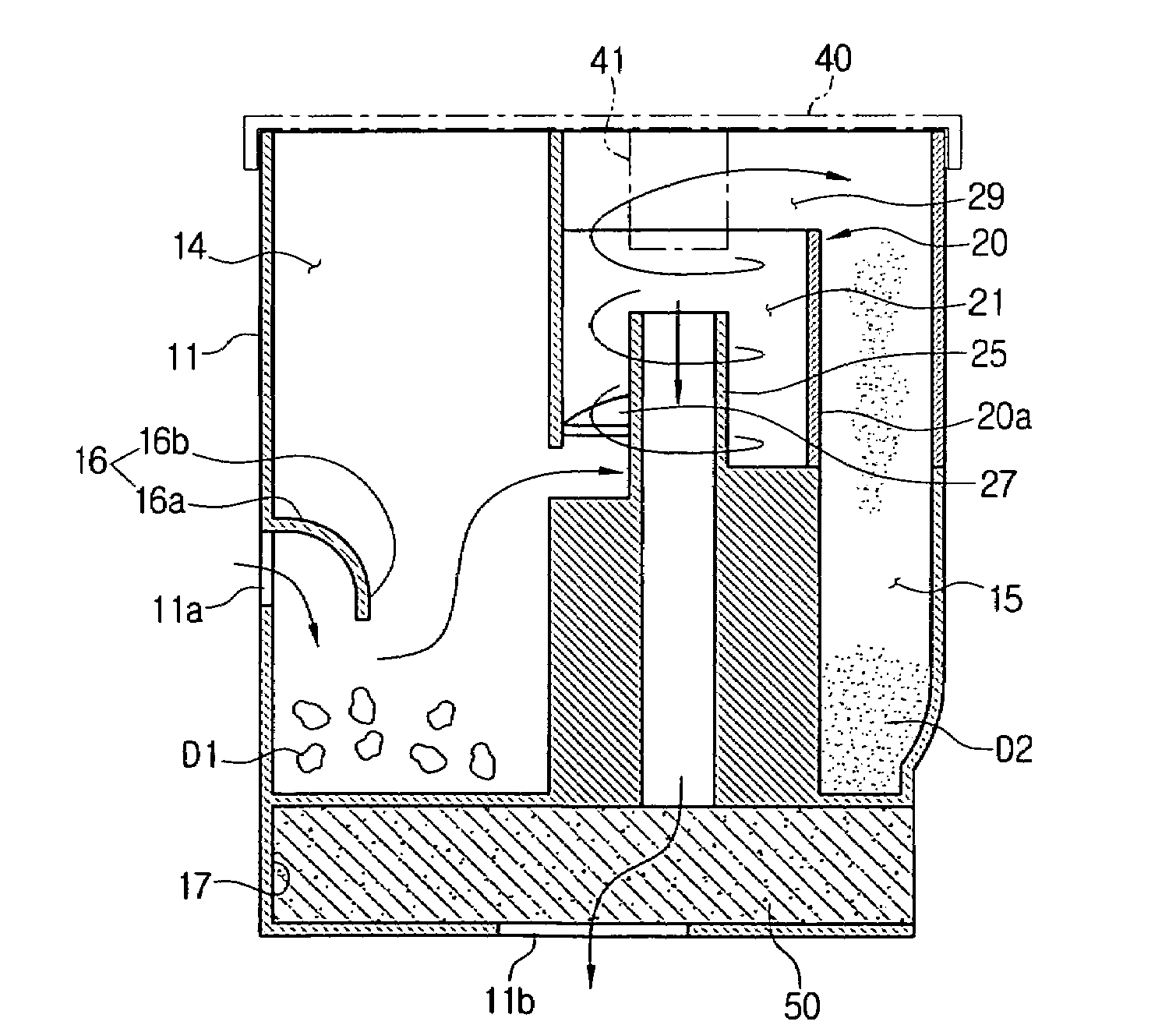
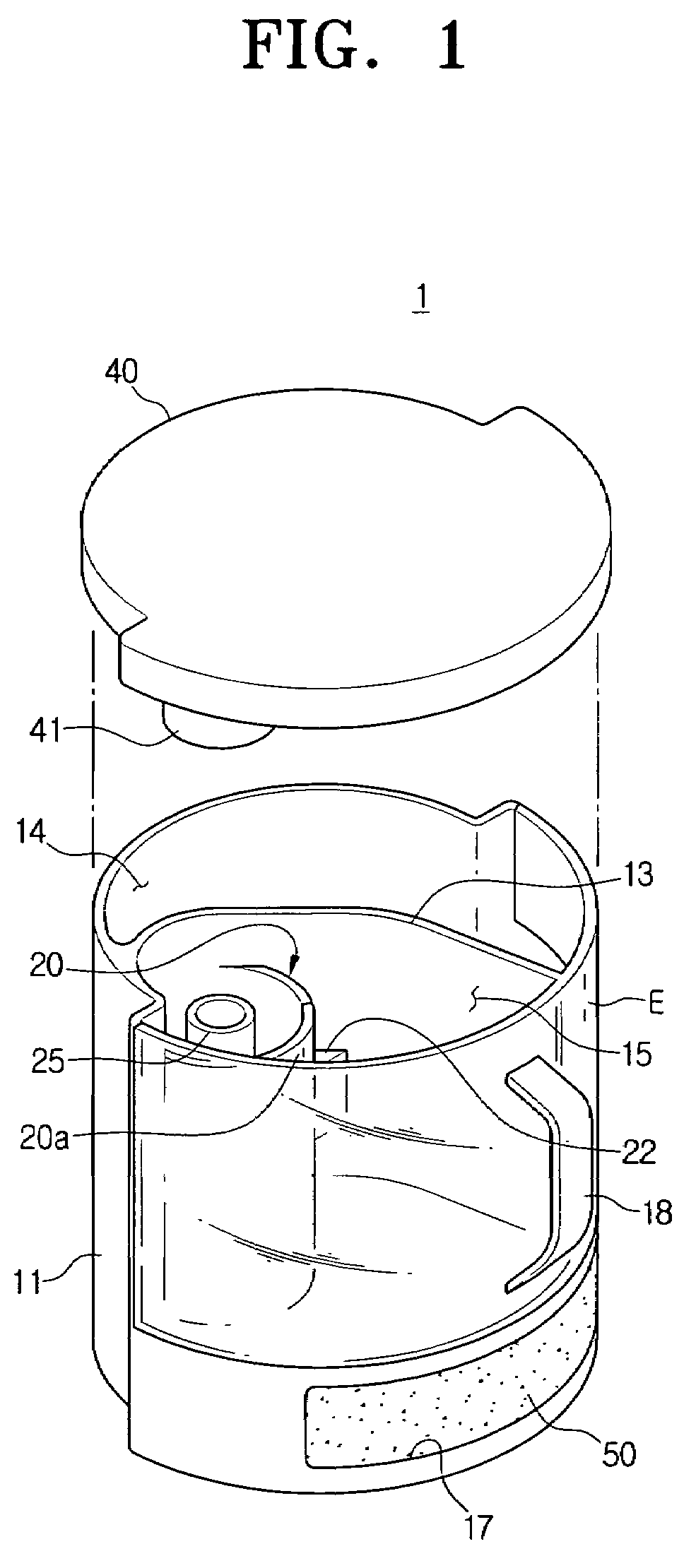
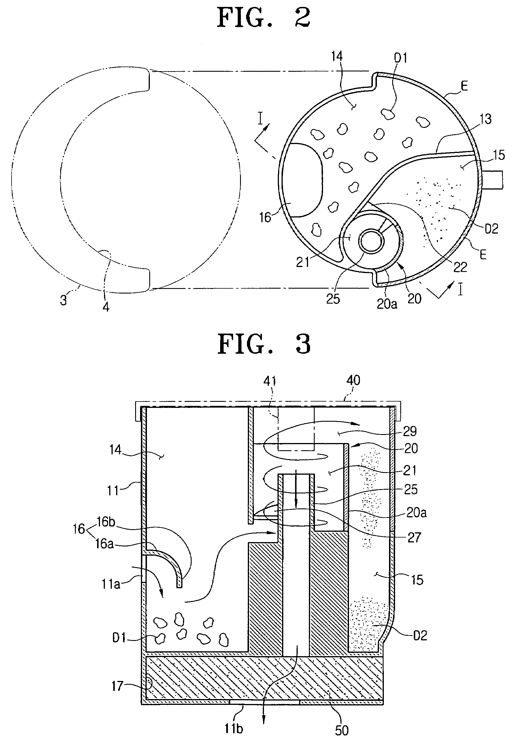
[0029]FIG. 1 is a perspective view of a dust collecting apparatus for a vacuum cleaner according to the present disclosure, FIG. 2 is a plan view of the dust collecting apparatus in which a cover shown in FIG. 1 is removed and FIG. 3 is a cross-sectional view taken along a line I-I of FIG. 2.

[0030]As shown in FIGS. 1 and 2, the dust collecting apparatus 1 according to the first embodiment of the present disclosure includes a dust canister body 11, first and second dust separating chambers 14 and 15, an inertia blocking plate 16, a cyclone body 20 and a cover 40.

[0031]As shown in FIG. 3, when a rear side of the dust canister body 11 is disposed at a concaved part 4 of a cleaner body 3, a front side of the dust canister body 11 becomes an exposed side E which is exposed to the outside of the cleaner body 3. The dust canister body 11 is formed with an inlet port 11a, through which air is flowed in, at the rear side thereof. In this case, the inlet port 11a is connected with a suction b...

second embodiment

[0039]FIG. 4 a plan view of the dust collecting apparatus for vacuum cleaner according to the present disclosure.

[0040]As shown in FIG. 4, the dust collecting apparatus according to the second embodiment has the same structure as in the first embodiment except a fact that a part of the cyclone body 120 is eccentrically disposed at the second dust separating chambers 15 so as to be protruded from the dust canister body 11 to the outside. That is, the cyclone body 120 is eccentrically disposed at one side of the second dust separating chamber 15 so as to have a protruded portion 126. Preferably, the protruded portion 126 is formed of the transparent material so that the user can see through the cyclone body 120. In this case, since the dust collecting apparatus 1 has the protruded portion 126, the dust collection chamber 11 can ensure availability of a space for collecting the dust into the dust collection chamber 11 as a space corresponding to the protruded portion 126. Therefore, it...

third embodiment

[0042]FIG. 5 is a plan view of the dust collecting apparatus for vacuum cleaner according to the present disclosure.

[0043]As shown in FIG. 5, the dust collecting apparatus according to the third embodiment has the same structure as in the first embodiment except a position that the cyclone body 220 is eccentrically disposed in the second dust separating chamber 15. That is, the cyclone body 220 is eccentrically disposed at one side of the second dust separating chamber 15 so as to have a common portion 226 which is integrally contacted with the exposed side E of the dust canister body 11.

[0044]Therefore, in the second and third embodiment, since the cyclone body 120, 220 is not apart from the exposed side E of the dust canister body 11 by having the protruded portion 126 or the common portion 226, it is prevent that the cyclone body 120, 220 is invisible by the collected dust and dirt. Therefore, the user can see more clearly the flow of the dirt or dust within the cyclone body 120,...


PUM

PropertyMeasurementUnit
gravityaaaaaaaaaa
centrifugal forceaaaaaaaaaa
transparentaaaaaaaaaa

Abstract

Disclosed is a dust collecting apparatus is provided that includes a dust canister body, a part of which becomes an exposed side exposed outside a cleaner body. The cleaner body has a first dust separating chamber for separating large-sized dirt and second dust separating chamber for collecting fine dust; a cyclone body having a cyclone chamber which separates the fine dust from the air passing through the first dust separating chamber; and an outlet pipe protruding from lower surfaces of the first and second cyclone bodies to upper sides of the first and second cyclone chambers, wherein at least a part of the exposed side of the dust canister body is made of a transparent material so as to simultaneously see through the first and second dust separating chambers, and at least a part of the cyclone body is made of the transparent material to see through the cyclone body.

Description

CROSS-REFERENCE TO RELATED APPLICATIONS[0001]This application claims the benefit of U.S. Provisional Application No. 60 / 814,332 filed on Jun. 16, 2006 in the United States Patent and Trademark Office, and the benefit of Korean Patent Application No. 10-2006-0069382 filed on Jul. 24, 2006 in the Korean Intellectual Property Office, the entire disclosures of which are incorporated herein by reference.BACKGROUND OF THE INVENTION[0002]1. Field of the Invention[0003]The present disclosure relates to a dust collecting apparatus for a vacuum cleaner, and more particularly to a dust collecting apparatus which can separate large-sized dirt and fine dust through a multi-stage process in twice.[0004]2. Description of the Related Art[0005]A dust collecting apparatus provided in a vacuum cleaner is to separate dirt and dust from drawn-in external air. Recently, a so-called cyclone dust collecting apparatus, which does not use a dust envelope and can be used semipermanently is used widely. In the...

Claims


Application Information

Patent Timeline
Patent Type & Authority Patents(United States)
IPC IPC(8): B01D50/00
CPCA47L9/102A47L9/165A47L9/1683A47L9/1608A47L9/1666A47L9/10A47L9/16
Inventor OH, JANG-KEUN
Owner SAMSUNG GWANGJU ELECTRONICS CO LTD
Why Eureka
Try Eureka