Apparatus and method for reducing shear loading on elements connecting an axle and a chassis of a vehicle

a technology of axles and chassis, applied in the direction of mechanical machines/dredgers, rigid support of bearing units, manufacturing tools, etc., can solve the problems of increasing variance and non-uniformity between individual vehicles of mass produced vehicles, misposition of surface and mounting pads located on weldments, and skewed orientation, so as to reduce or straighten out at least some of any shear forces acting in adjacent regions, increase variance and non-uniformity, and reduce the effect of s

Active Publication Date: 2008-06-10
BLUE LEAF I P INC
View PDF26 Cites 2 Cited by
  • Summary
  • Abstract
  • Description
  • Claims
  • Application Information

AI Technical Summary

Benefits of technology

[0006]According to a preferred aspect of the invention, a plurality of locating surfaces or mounting pads are located on the chassis against which the axle can be urged so as to be positioned in a desired assembly or mounting position in relation to the chassis. The chassis and axle are connected and fixed in relation one to the other in the desired position by a plurality of connectors which can be, for instance, common commercially available bolts or other fasteners, extending in a predetermined or first direction. Wedge surfaces are located on the chassis and on the axle, respectively, disposed so as to be in opposing relation at a predetermined angle one relative to the other and define a space therebetween extending in a direction of shear loading or second direction, at least generally transverse to the predetermined or first direction, to be exerted on predetermined ones of the connectors when the axle is in the desired position in relation to the chassis. A tapered block or wedge member having oppositely facing outer surfaces angularly related at about the predetermined acute angle is positionable in the space between the wedge surfaces, so as to face at least substantially in the direction of the shear loading or second direction, and has an extent in that direction between the outer surfaces thereof sufficiently large so as to simultaneously contact the wedge surfaces when the block is positioned in the space. An adjusting member preferably connects the tapered block to at least one of the chassis and the axle, and is adjustable for moving the block to a position for applying forces against the wedge surfaces to urge the wedge surfaces apart. This can also operate to reduce or straighten out some of any warpage, distortion and / or deformation of the adjacent region of the chassis, and reduce at least some of any shear forces acting against the connectors connecting the axle and chassis. Additional connectors extending in the second direction of the shear loading, can then be tightened so as to exert compressive forces against the tapered block, without applying additional shear loads against the original connectors. The additional fasteners will also hold the tapered block in position, and further secure the chassis and axle together.
[0007]As discussed above, under the Background Art, it has been observed that locating surfaces and mounting pads located on weldments may be mis-positioned and / or mis-oriented or skewed relative to a nominal or desired position and orientation thereof, as a result of conditions such as warpage resulting from stress changes due to the heat generated by welding, manufacturing tolerances, and the like, such that mating locating surfaces and / or pads which are to be brought into abutment are not perfectly parallel in their free states. As noted, as one alternative, it may be possible that such surfaces and pads could be machined to attain proper position and orientation, and / or shims could be used. However, both of these are time consuming and costly. They also increase variances and non-uniformity between individual ones of mass produced vehicles. By using the apparatus and method of the invention, the axle can be properly fit-up to the vehicle's chassis, preferably by applying torques to the connectors for bringing the opposing locating surfaces or mounting pads together in the desired abutting relation, which, as a consequence, will often cause shear loads or forces to be applied to the connectors. By forceably moving the tapered block or wedge member of the invention in contact with the wedge surfaces, the shear forces can be counteracted and reduced or relieved. Then, the additional connectors extending in the direction of the shear forces can be tightened without applying shear loading to the existing connectors extending in the first direction.
[0008]As attendant advantages of the preferred apparatus and method of the invention as just described, fit-up of an axle and chassis of a vehicle is simplified and streamlined, need for machining of locating surfaces and / or mounting pads on the chassis weldment and shimming is eliminated, and shear loads or forces acting on connectors are substantially reduced. Further, with the counteraction or reduction of shear forces, the forces transmitted between the axle and chassis will be more normal to the locating surfaces or mounting pads.

Problems solved by technology

As discussed above, under the Background Art, it has been observed that locating surfaces and mounting pads located on weldments may be mis-positioned and / or mis-oriented or skewed relative to a nominal or desired position and orientation thereof, as a result of conditions such as warpage resulting from stress changes due to the heat generated by welding, manufacturing tolerances, and the like, such that mating locating surfaces and / or pads which are to be brought into abutment are not perfectly parallel in their free states.
However, both of these are time consuming and costly.
They also increase variances and non-uniformity between individual ones of mass produced vehicles.

Method used


Image

  • Apparatus and method for reducing shear loading on elements connecting an axle and a chassis of a vehicle
  • Apparatus and method for reducing shear loading on elements connecting an axle and a chassis of a vehicle
  • Apparatus and method for reducing shear loading on elements connecting an axle and a chassis of a vehicle

Examples


Embodiment Construction

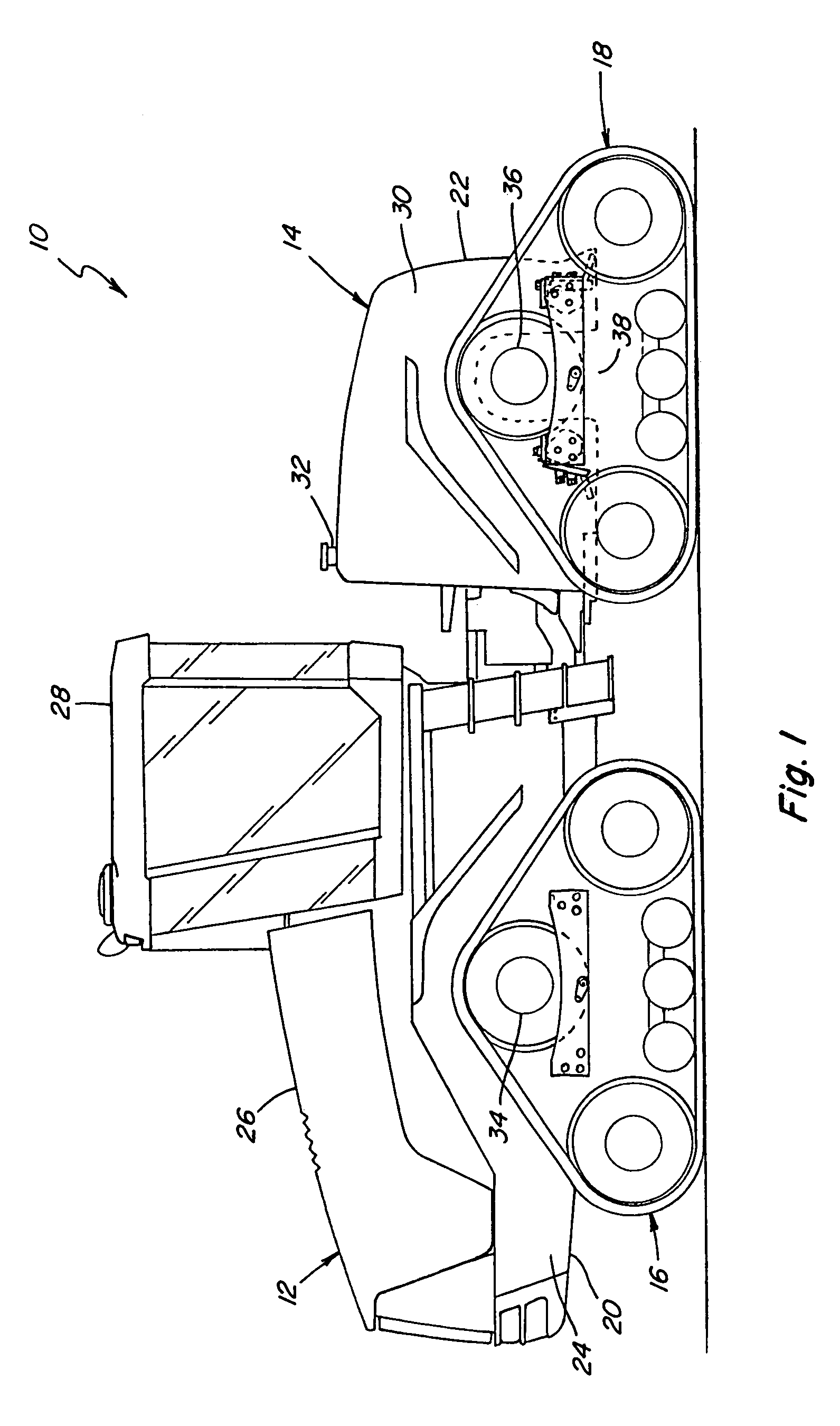
[0015]Referring now to the drawings, in FIG. 1, a vehicle 10, which is a four track drive tractor typically used for such purposes as agriculture, earthmoving, construction, and the like, is shown. Vehicle 10 includes a front segment 12 and a rear segment 14, connected together for pivotal movement one relative to the other, about a central pivotal axis (not shown) therebetween. Front segment 12 is drivingly supported by a pair of front tracks 16 on opposite sides thereof, and rear segment 14 is drivingly supported by a pair of rear tracks 18 on either side thereof. Front segment 12 includes a front chassis 20, and rear segment 14 includes a rear chassis 22. Front chassis 20 includes a pair of spaced apart, fore to aft and upwardly extending side chassis plates, represented by left side chassis plate 24. An engine (not shown) is supported between the chassis side plates under a front hood 26, and an operator cab 28 is supported on the side chassis plates aft of hood 26. Rear chassis...


PUM

PropertyMeasurementUnit
acute angleaaaaaaaaaa

Abstract

Referring more particularly to FIG. 4, the present invention red ices such shear loading on the bolts, by utilizing a wedge member or a tapered block 106, inserted and wedged into a space 108 between wedge surfaces 70 and 88, and having oppositely facing outer surfaces 110 and 112 thereby placed into abutment with those surfaces, respectively, so as to exert a fore and aft directed force against those surface, denoted by arrows C, effectively acting to push those surfaces apart and counteracting the shear loads B. Such forces will also act in opposition to and reduce tensile loads acting on bolts 100. Tapered block 106 has at least one passage 114 therethrough (FIG. 3) for the passage of bolts 104 therethrough, to allow insertion of those bolts into threaded holes 98 and tightening those bolts to exert compressive forces against tapered block 106, denoted by arrows D, for holding that block in position. This may also be sufficient to apply a tensile load bolts 100, which are preferably at least generally longitudinally aligned therewith as shown. As a result, a force equilibrium condition can be achieved, which can significantly and predictably reduce and control shear forces acting against the bolts or other connectors for connecting axle housing 74 to the side plates 24 of chassis 22.

Description

TECHNICAL FIELD[0001]This invention relates generally to an apparatus and method for mounting or assembling an axle or axle housing and a chassis of a vehicle, and more particularly, to an apparatus and method which improves fit-up between a chassis and axle and reduces shear loads exerted against connectors such as bolts or the like connecting the axle and chassis.BACKGROUND ART[0002]Commonly, a heavy-duty vehicle, such as, but not limited to, a work machine such as a tractor, and more particularly, an all-wheel or all-track drive tractor for agriculture, earthmoving and other uses, has a chassis comprised of one or more weldments. Such weldments typically include a plurality of mounting or locating pads and / or plates nominally positioned for surface-to-surface abutting contact with mating mounting pads and / or surfaces on an axle, axle housing, or axle assembly, hereinafter referred to as an “axle”. The axle may be of wrought metal, cast, and / or welded construction. Typically, the ...

Claims


Application Information

Patent Timeline
Patent Type & Authority Patents(United States)
IPC IPC(8): B62D21/00B62D21/10B62D21/09
CPCB62D55/0655B62D55/125Y10T29/53922
Inventor RASSET, JOHN T.GARBERG, BRYAN J.ZURN, DANIEL J.LYKKEN, THOMAS G.OVERMANN, ROBERT J.VIK, BRIAN D.
Owner BLUE LEAF I P INC
Why Eureka
Try Eureka