Method of enabling two-state operation of electronic toll collection system

a technology two-state operation, applied in the field of electronic toll collection system communication method and system, can solve the problem that the transponder cannot be easily changed or modified

Inactive Publication Date: 2008-06-17
MARK IV INDS
View PDF54 Cites 65 Cited by
  • Summary
  • Abstract
  • Description
  • Claims
  • Application Information

AI Technical Summary

Problems solved by technology

In existing systems, this may be difficult because there are thousands of existing transponders deployed within the marketplace.
These existing transponders may not be easily changed or modified.

Method used


Image

  • Method of enabling two-state operation of electronic toll collection system
  • Method of enabling two-state operation of electronic toll collection system
  • Method of enabling two-state operation of electronic toll collection system

Examples


Embodiment Construction

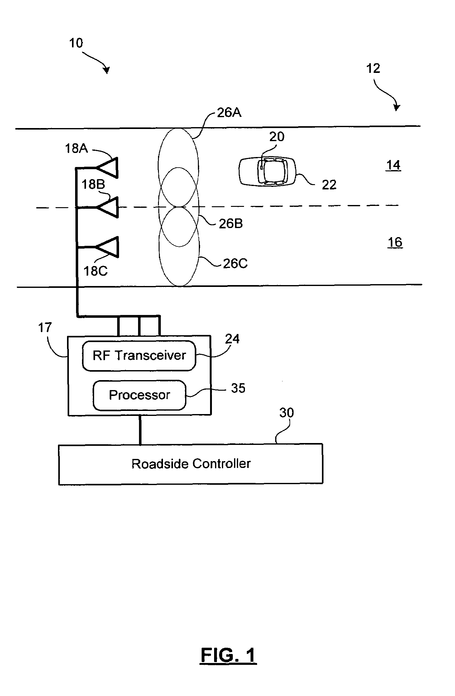
[0022]Reference is first made to FIG. 1, which shows, in diagrammatic form, an electronic toll collection system 10. In this example embodiment, the electronic toll collection system 10 is used in connection with a roadway 12 having first and second adjacent lanes 14 and 16. It will be appreciated that in other embodiments the electronic toll collection system 10 may be used in connection with single lane roadways, multi-lane roadways, toll plazas, or other road configurations. The electronic toll collection system 10 may be used in a gated embodiment, wherein the vehicles enter a toll collection area and are signaled, such as by a gate or light, when they are permitted to proceed. The electronic toll collection system 10 may also be used in an open road embodiment, wherein the vehicles are not required to stop or slow down in the toll collection area.

[0023]The electronic toll collection system 10 includes a reader 17 connected to a set of antennas 18 (shown individually as 18A, 18B...


PUM


Abstract

A method and system for communicating state information from a transponder to a reader. The transponder outputs linearly polarized RF signals having either a first polarization, such as horizontal, or a second polarization, such as vertical. The polarization is selected so as to indicate a first state or a second state. The reader detects whether received RF signals have the first polarization or the second polarization, and thereby determines the state of the transponder. In some embodiments, the reader may include two linearly polarized antennas, one with the first polarization and one with the second polarization, for receiving the RF signals from the transponder and determining the polarization of the received RF signals. The system may be implemented within an electronic toll collection system, wherein the transponders are affixed to the interior of vehicle windshields using a rotatable mounting mechanism having two selectable positions.

Description

FIELD OF THE INVENTION[0001]The present invention relates to an electronic toll collection system and, in particular, to a method and system for communicating state information in an electronic toll collection system.BACKGROUND OF THE INVENTION[0002]Electronic toll collection systems conduct toll transactions electronically using RF communications between a vehicle-mounted transponder (a “tag”) and a stationary toll plaza transceiver (a “reader”). An example of an electronic toll collection system is described in U.S. Pat. No. 6,661,352 issued Dec. 9, 2003 to Tiernay et al., and owned in common with the present application. The contents of U.S. Pat. No. 6,661,352 are hereby incorporated by reference.[0003]In a typical electronic toll collection (ETC) system, the reader broadcasts a polling or trigger RF signal. A transponder on a vehicle passing through the broadcast area or zone detects the polling or trigger signal and responds with its own RF signal. The transponder responds by s...

Claims


Application Information

Patent Timeline
Patent Type & Authority Patents(United States)
IPC IPC(8): G08B13/14
CPCG06K7/10346G06K19/0723
Inventor TANG, WAI-CHEUNGHO, THUA VAN
Owner MARK IV INDS
Why Eureka
Try Eureka