Apparatus for putting a loading object in mouth by motion of jaw

Inactive Publication Date: 2008-06-24
KAMEYA SHUNSUKE
View PDF7 Cites 1 Cited by
  • Summary
  • Abstract
  • Description
  • Claims
  • Application Information

AI Technical Summary

Benefits of technology

[0021](d) To provide an apparatus which can also use as an op

Problems solved by technology

However, there are the following problems with this general way.
This conventional technology is able to blow the whistle quickly, but that the technology has a problems of actual use.(a) The whistle can not be adjusted if a hand is not free.(b) Without

Method used


Image

  • Apparatus for putting a loading object in mouth by motion of jaw
  • Apparatus for putting a loading object in mouth by motion of jaw
  • Apparatus for putting a loading object in mouth by motion of jaw

Examples


Embodiment Construction

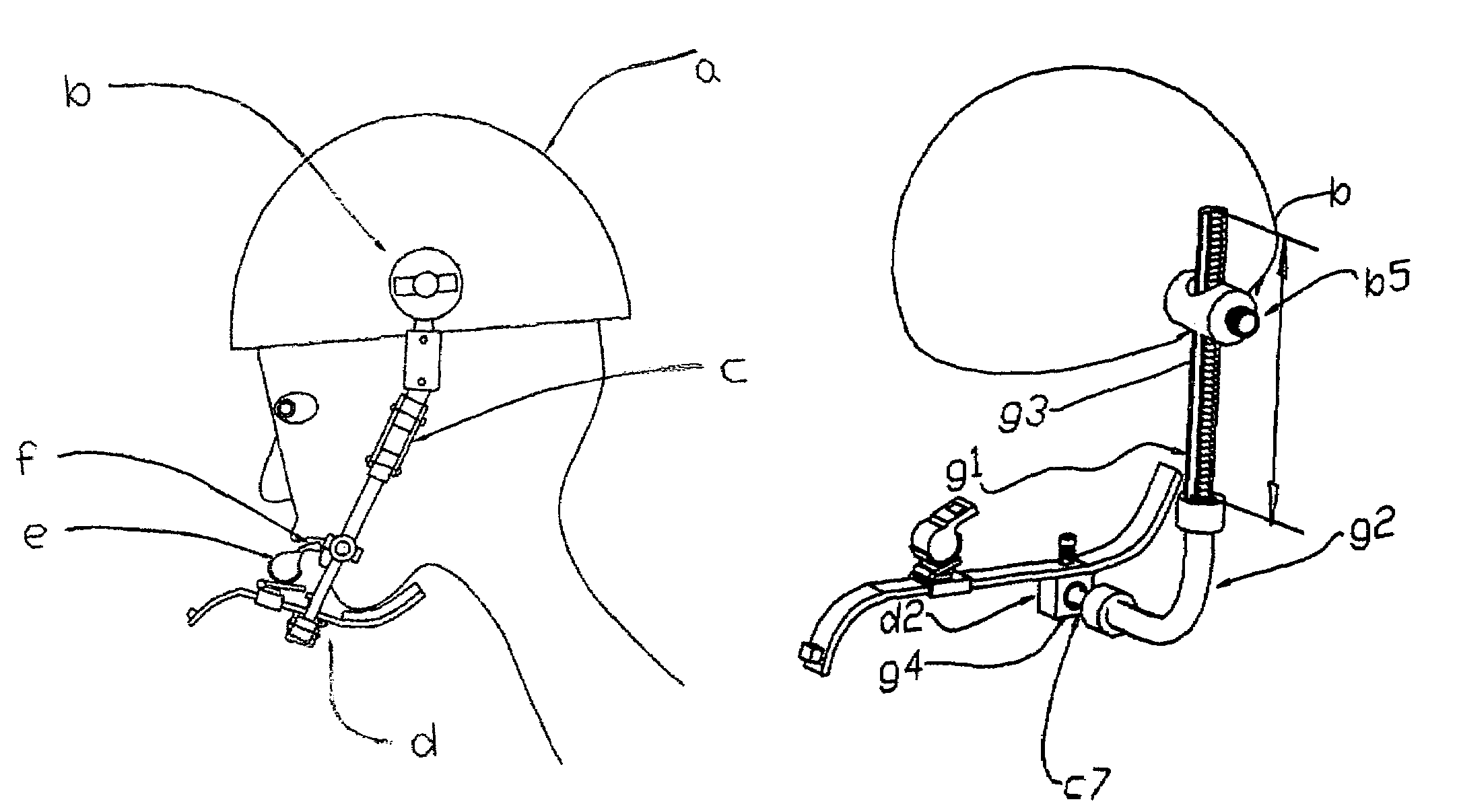
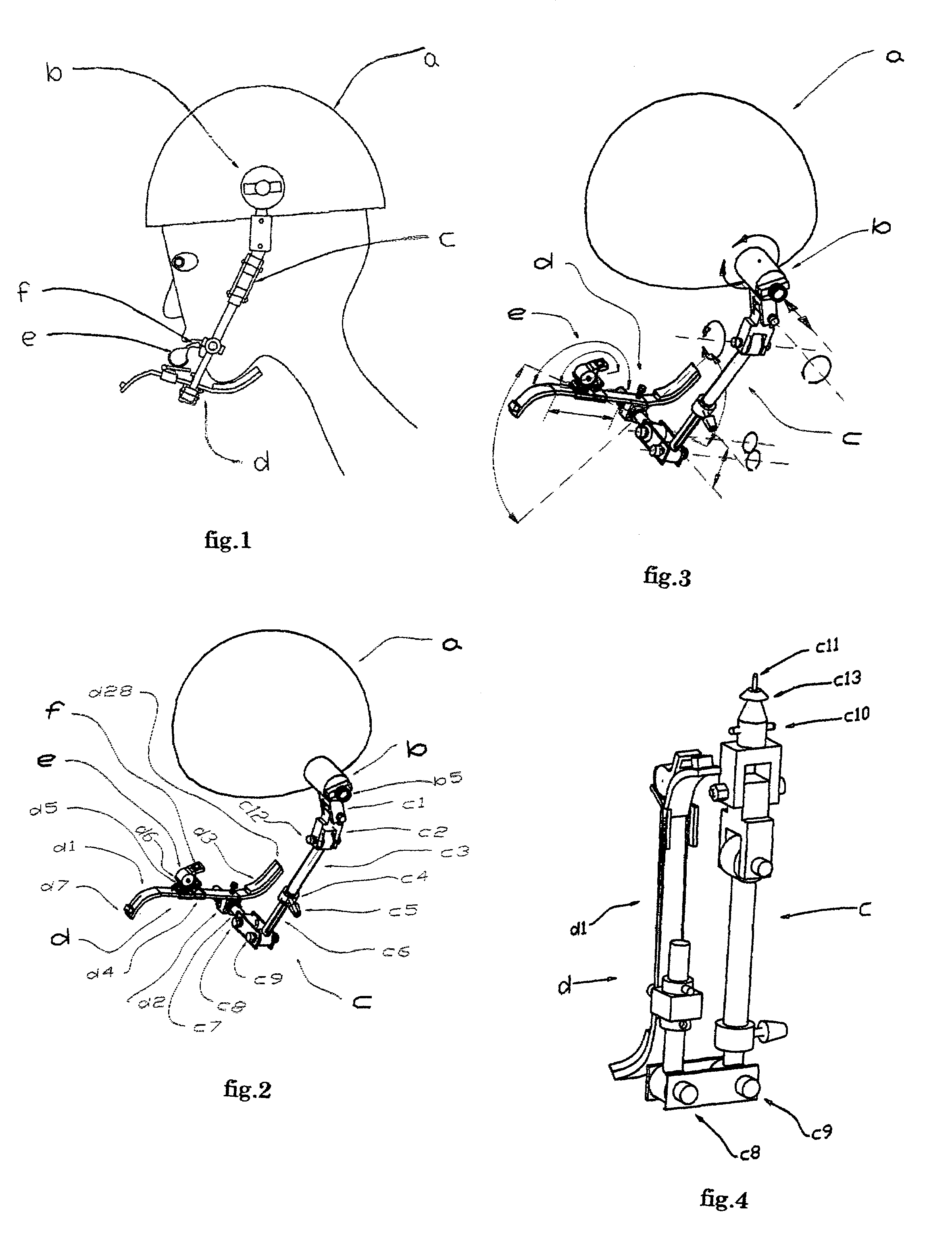
[0035]In accordance with the present invention, a loading object putting apparatus (a, b, c, d, e) puts a loading object in the wearer's mouth by movement of the wearer's jaw. FIG. 1 is a side view of the loading object putting apparatus (a, b, c, d, e) being used by user. In this FIG. 1, a wearer supplies the loading object (e) to the wearer's a mouth by the lever apparatus (d) swung by motion of the wearer's jaw.

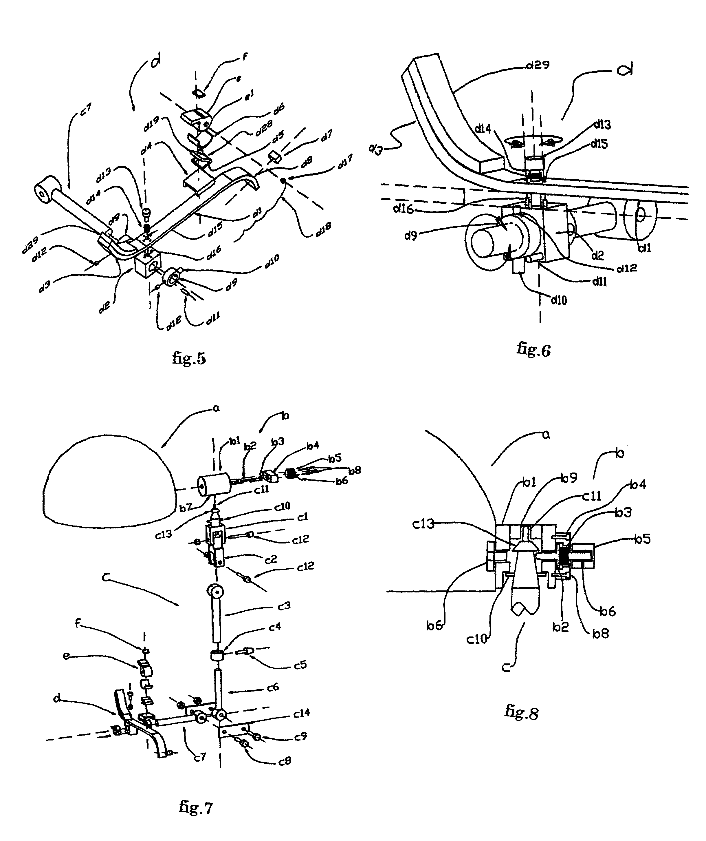
[0036]FIG. 2 is a perspective view of the loading object putting apparatus (a, b, c, d, e). The putting apparatus has a hard hat (a, b, c, d, e) (a), an arm connection means (b), an arm (c), lever apparatus (d), the loading object (e), and a primary detecting element (1).

[0037]FIG. 3 shows the motion of the moving part of FIG. 2 by the arrow. The arm connecting means (b) is attached on the side wall of the hard hat (a). The arm connecting means (b) contains the knob (b5). The knob (b5) moves in the direction of the arrow shown in FIG. 3, and makes the arm (c) a detachable ...


PUM


Abstract

A loading object putting apparatus (a, b, c, d, and e) puts a loading object (e) in mouth by movement of jaw. The loading object putting apparatus (a, b, c, d, e) includes a headgear (a), an arm connecting means (b), an arm (c), a lever apparatus (d) rocked by a jaw, and the loading object (e).

Description

FEDERALLY SPONSORED RESEARCH[0001]Not ApplicableSEQUENCE LISTING OR PROGRAM[0002]Not ApplicableBACKGROUND OF THE INVENTION[0003]1. Field of Invention[0004]This invention relates to an apparatus for putting a Loading object in a wearer's mouth by movement of the wearer's lower jaw without using hands.[0005]2. Prior Art[0006]In order to make it easy to use, the whistle has been used by hanging on the head via strap.However, there are the following problems with this general way.[0007](a) Finding the whistle is hard, so it takes some time to blow the whistle.[0008](b) The whistle cannot be used if the user's hands are not free.[0009]U.S. Pat. No. 5,504,943 describes a headgear having an attachable whistle.This conventional technology is able to blow the whistle quickly, but that the technology has a problems of actual use.[0010](a) The whistle can not be adjusted if a hand is not free.[0011](b) Without electric power, loud sound can't be made.[0012]In general art, putting a in the mout...

Claims


Application Information

Patent Timeline
IPC IPC(8): A42B1/24A61C8/00
CPCA42B1/24
Inventor KAMEYA, SUNNSUKE
Owner KAMEYA SHUNSUKE
Why Eureka
Try Eureka