
Method and system for 3D comb filtering of a video signal

a video signal and comb filtering technology, applied in the field of video signal processing, can solve the problems of reducing vertical bandwidth and incurring losses, and achieve the effect of minimizing or eliminating artifacts and maximizing output video quality

Active Publication Date: 2008-06-24
AVAGO TECH INT SALES PTE LTD
View PDF3 Cites 2 Cited by
  • Summary
  • Abstract
  • Description
  • Claims
  • Application Information

AI Technical Summary

Benefits of technology

[0023]Another aspect of the invention may provide a machine-readable storage, having stored thereon, a computer program having at least one code section executable by a machine, thereby causing the machine to perform the steps as described above for separating luma and chroma components in a composite video signal.
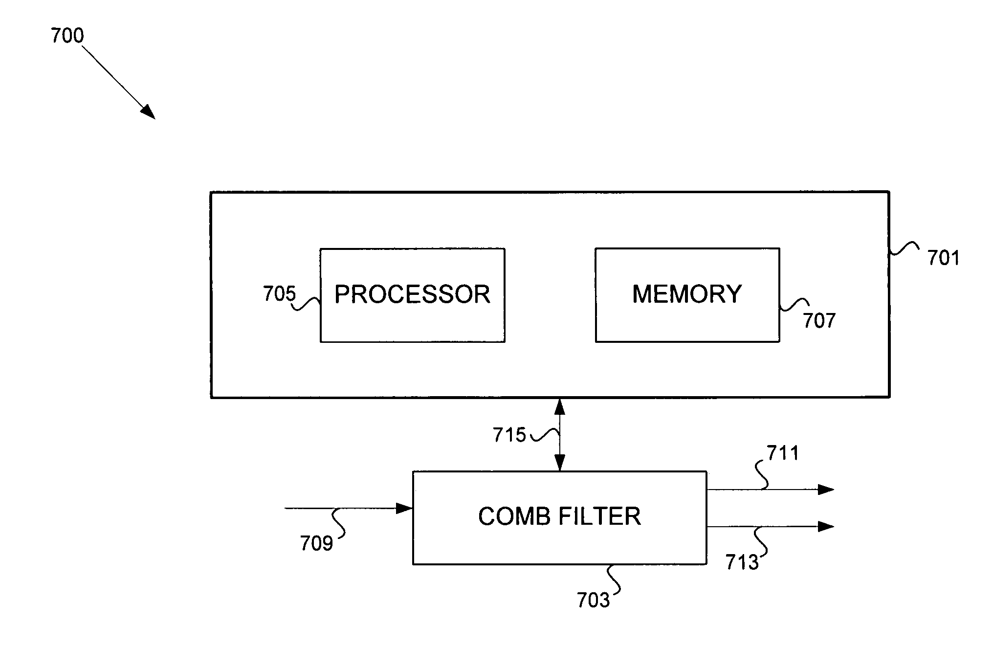
[0026]The processor may be adapted to comb temporally, if the determined direction of least bandwidth is among corresponding in-phase pixels in the first pixel line of the first video frame and in the first pixel line of the second video frame. If the determined direction of least bandwidth is among corresponding one-half cycle phase-shifted video samples in the first pixel line of the first video frame and in the first pixel line of the second video frame for a luma-only video signal, the at least one processor may comb temporally. The processor may comb in a horizontal direction and a vertical direction for the first video frame. The processor may blend the combing in the horizontal direction and in the vertical direction, and combing in a temporal direction for the first video frame in order to maximize output video quality and minimize or eliminate artifacts.

Problems solved by technology

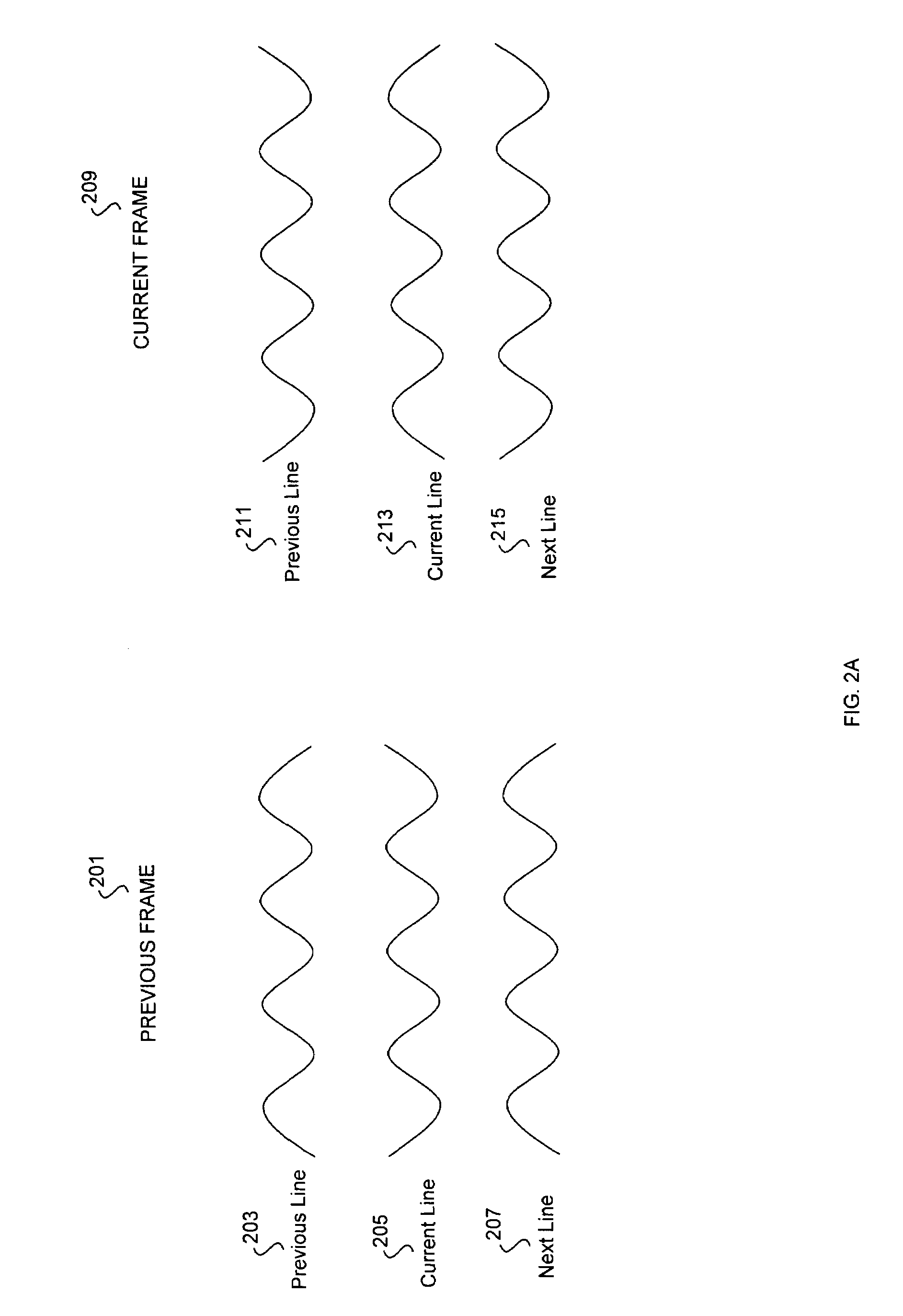
During separation of the luma and chroma components, there are three bandwidth directions that may incur losses in the separation process and in the separated signal.
However, vertical combing may result in a reduced vertical bandwidth.

Method used


Image

  • Method and system for 3D comb filtering of a video signal
  • Method and system for 3D comb filtering of a video signal
  • Method and system for 3D comb filtering of a video signal

Examples


Embodiment Construction

[0043]Certain aspects of the invention may be found in a method and system for separating luma and chroma components in a composite video signal. Video samples, or true pixels, as well as a plurality of interpolated pixels for corresponding video samples, may be generated for a specific first video frame and a second video frame. A direction of least bandwidth may be determined among the video samples and the interpolated pixels within a pixel line, between pixel lines in the same video frame, and between pixel lines in two adjacent video frames. Horizontal, vertical and / or temporal combing may then be utilized in the determined direction of least bandwidth.

[0044]Certain other aspects of the invention may be found in a method and system for 3D comb filtering of a video signal. During separation of the chroma and luma video components in a composite video signal feed, combing horizontally, combing vertically and / or combing temporally may be utilized to achieve the chroma and luma sep...


PUM


Abstract

Methods and systems for 3D comb filtering of a video signal are provided. Aspects of the method may include generating a plurality of interpolated pixels for corresponding video samples for a first video frame, determining at least one direction of least bandwidth among the video samples and the interpolated pixels, and blending combing according to the determined direction of least bandwidth. A plurality of interpolated pixels for corresponding video samples may be generated in a first pixel line of the first video frame. The plurality of interpolated pixels in the first pixel line may be generated, so that each of the plurality of interpolated pixels in the first pixel line is one quarter cycle phase-shifted from a corresponding adjacent pixel in the first pixel line.

Description

CROSS-REFERENCE TO RELATED APPLICATIONS / INCORPORATION BY REFERENCE[0001]This application makes reference to, claims priority to, and claims the benefit of U.S. Provisional Application Ser. No. 60 / 540,698, filed Jan. 30, 2004 and entitled “3D Comb Filter.”[0002]This application makes reference to:[0003]U.S. application Ser. No. 10 / 943,587 filed Sep. 17, 2004;[0004]U.S. application Ser. No. 10 / 943,593 filed Sep. 17, 2004;[0005]U.S. application Ser. No. 10 / 943,596 filed Sep. 17, 2004;[0006]U.S. application Ser. No. 10 / 869,395 filed Jun. 16, 2004; and[0007]U.S. application Ser. No. 10 / 943,641 filed Sep. 17, 2004.[0008]The above stated applications are hereby incorporated herein by reference in their entirety.FIELD OF THE INVENTION[0009]Certain embodiments of the invention relate to processing of video signals. More specifically, certain embodiments of the invention relate to a method and system for 3D comb filtering of a video signal.BACKGROUND OF THE INVENTION[0010]A composite video si...

Claims


Application Information

Patent Timeline
Patent Type & Authority Patents(United States)
IPC IPC(8): H04N9/78H04N9/77
CPCH04N9/78
Inventor JOHNSON, SHAWN V.
Owner AVAGO TECH INT SALES PTE LTD
Learn More