Media stream image transmission method and system

A media streaming and image technology, applied in the field of communication, can solve problems such as increasing compatibility costs, achieve high image quality, improve user experience, and maximize video quality

Active Publication Date: 2018-06-01
山东爱特云翔信息技术有限公司
View PDF4 Cites 0 Cited by
  • Summary
  • Abstract
  • Description
  • Claims
  • Application Information

AI Technical Summary

Problems solved by technology

[0004] The technical problem to be solved by the present invention is to provide a method and system for media stream image transmission, which is used to solve the problem that the existing media stream adaptive transmission method completes the transmission through selective loss of frames, which requires cooperation between multiple objects. The problem of adding additional compatibility costs

Method used


Image

  • Media stream image transmission method and system
  • Media stream image transmission method and system
  • Media stream image transmission method and system

Examples


Embodiment 1

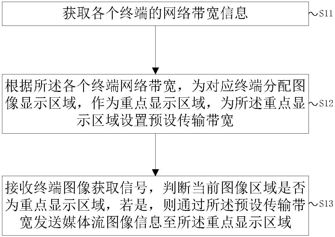
[0047] This embodiment provides a method for media stream image transmission, such as figure 1 shown, including steps:

[0048] S11: Obtain network bandwidth information of each terminal;

[0049] S12: According to the network bandwidth of each terminal, assign an image display area to the corresponding terminal as a key display area, and set a preset transmission bandwidth for the key display area;

[0050] S13: Receive a terminal image acquisition signal, determine whether the current image area is a key display area, and if so, send media stream image information to the key display area through the preset transmission bandwidth.

[0051] In this embodiment, the server serves as the sending end and sends media stream image information to the terminal, and the terminal serves as the receiving end, which may be a network communication device with network bandwidth, such as a mobile phone, a computer, a TV, and the like.

[0052] In this embodiment, step S11 is to acquire net...

Embodiment 2

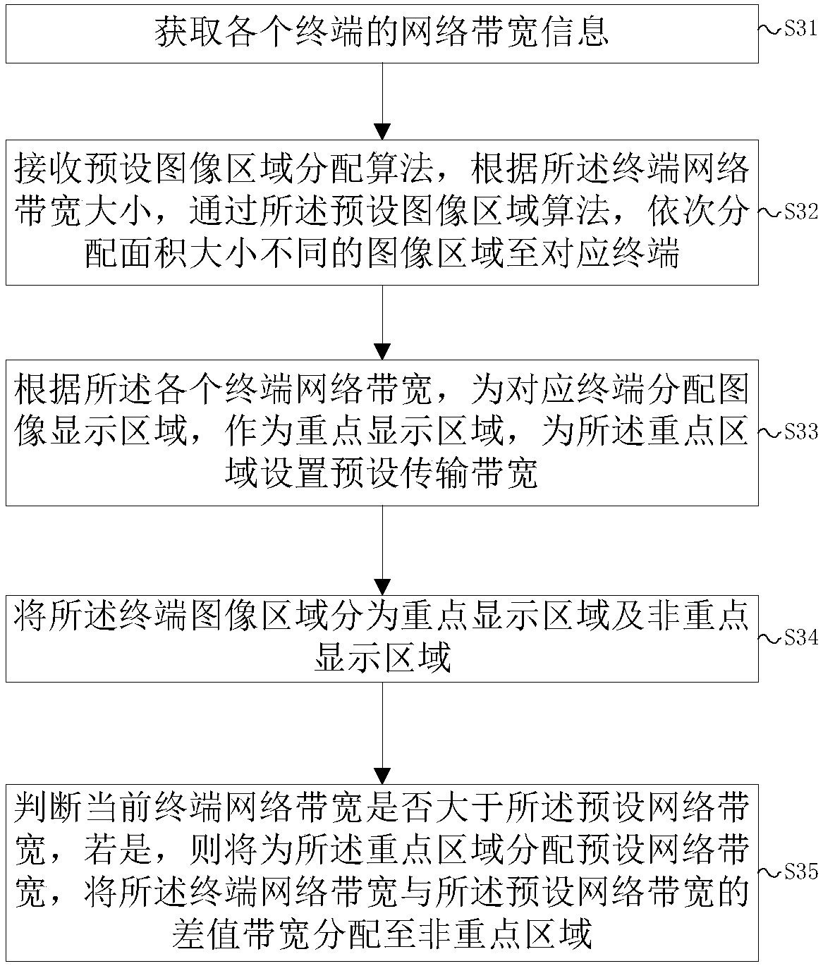
[0086] This embodiment provides a method for media stream image transmission, such as image 3 shown, including steps:

[0087] S31: Obtain network bandwidth information of each terminal;

[0088] S32: Receive a preset image area allocation algorithm, and sequentially allocate image areas with different sizes to corresponding terminals through the preset image area algorithm according to the size of the terminal network bandwidth;

[0089] S33: According to the network bandwidth of each terminal, allocate an image display area for the corresponding terminal as a key display area, and set a preset transmission bandwidth for the key area;

[0090] S34: Divide the terminal image area into a key display area and a non-key display area;

[0091] S35: Determine whether the current terminal network bandwidth is greater than the preset network bandwidth, if so, allocate the preset network bandwidth to the key area, and allocate the difference bandwidth between the terminal network b...


PUM


Abstract

The invention provides a media stream image transmission method and a media stream image transmission system, used for solving the problem that an existing media stream adaptive transmission method completes transmission by selectively losing frames, so that mutual cooperation between a plurality of objects is needed, and the additional compatibility cost is increased. The method comprises the steps of S1, acquiring network bandwidth information of each terminal; S2, according to the network bandwidth of each terminal, distributing an image display area for the corresponding terminal to serveas an important display area, and setting preset transmission bandwidth for the important display area; and S3, receiving a terminal image acquisition signal, judging whether a current image area is the important display area, if yes, sending media stream image information to the important display area via the preset transmission bandwidth. By using the method and the system provided by the invention, while the compatibility problem is solved, the video image quality of each terminal can be maximized under the limited network bandwidth environment, and the visual experience of the user is enhanced.

Description

technical field [0001] The present invention relates to the technical field of communication, in particular to a method and system for media stream image transmission. Background technique [0002] With the rapid development of the Internet and information technology, the digitalization and interaction of media services are increasing day by day, and users also expect to obtain higher-quality video and image experience or other media types of experience, but for users with limited terminal network bandwidth, in When performing media streaming, due to the limitation of network bandwidth, a good video experience cannot be obtained, and often video images will selectively lose frames, resulting in a decrease in video quality. [0003] In the case of limited network bandwidth, the existing media stream will be transmitted through selective loss of frames through the adaptive transmission method, which will bring poor visual experience to the user. At the same time, the adaptive ...

Claims


Application Information

Patent Timeline
Patent Type & Authority Applications(China)
IPC IPC(8): H04N21/2385H04N21/24H04N21/262H04N21/442H04N21/4728
CPCH04N21/2385H04N21/2402H04N21/26216H04N21/44209H04N21/44227H04N21/4728
Inventor 李祎蒋俊钢
Owner 山东爱特云翔信息技术有限公司
Why Eureka
Try Eureka