Method and system for controlling hourglass deformations of solid elements in finite element analysis

a finite element analysis and hourglass mode technology, applied in the direction of instruments, computation using non-denominational number representations, design optimisation/simulation, etc., can solve the problems of inability to integrate closed forms, inability to contribute to zero-energy modes, and inability to deformation due to zero-energy modes

Active Publication Date: 2008-06-24
ANSYS
View PDF5 Cites 24 Cited by
  • Summary
  • Abstract
  • Description
  • Claims
  • Application Information

AI Technical Summary

Benefits of technology

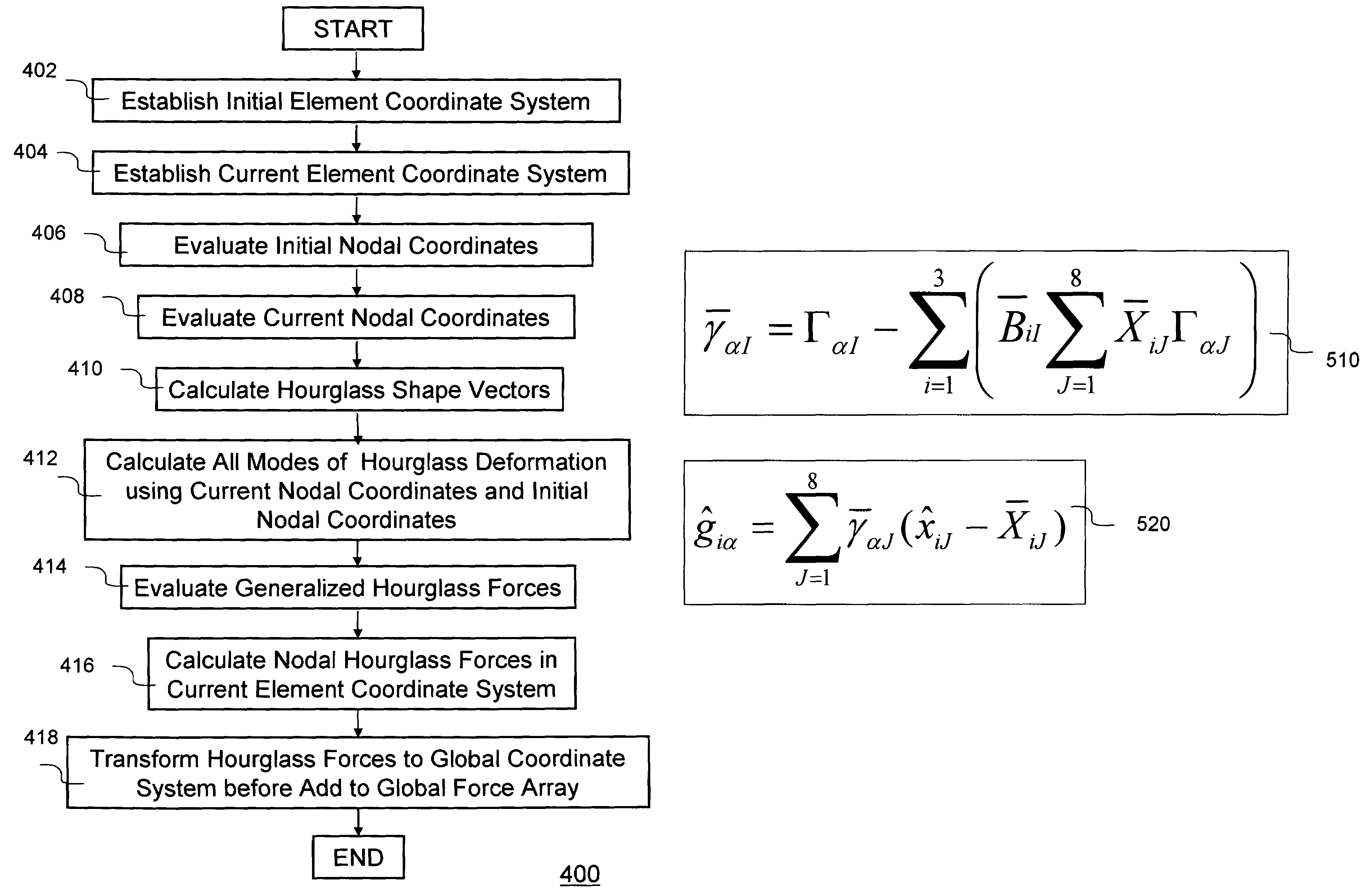
[0020]According to yet another aspect of the present invention, the set of nodal forces to resist hourglass deformation is designed to return to zero when the hourglass deformation returns to zero. In the exemplary tire simulation, this allows the tire to spring back to its initial geometry for any number of tire rotations. The present invention calculates the hourglass deformation by directly comparing the current geometry with the initial geometry. With this method, error cannot accumulate over time and elements can always spring back to their initial shape.
[0021]According to yet another aspect of the present invention, an embedded coordinate system is defined to transform and rotate with the element. This allows any amount of rigid body translation and rotation of the element to occur without affecting the hourglass deformation measure.

Problems solved by technology

For many materials, the stress field does not have a linear relationship to the strain field, so closed form integration is not possible.
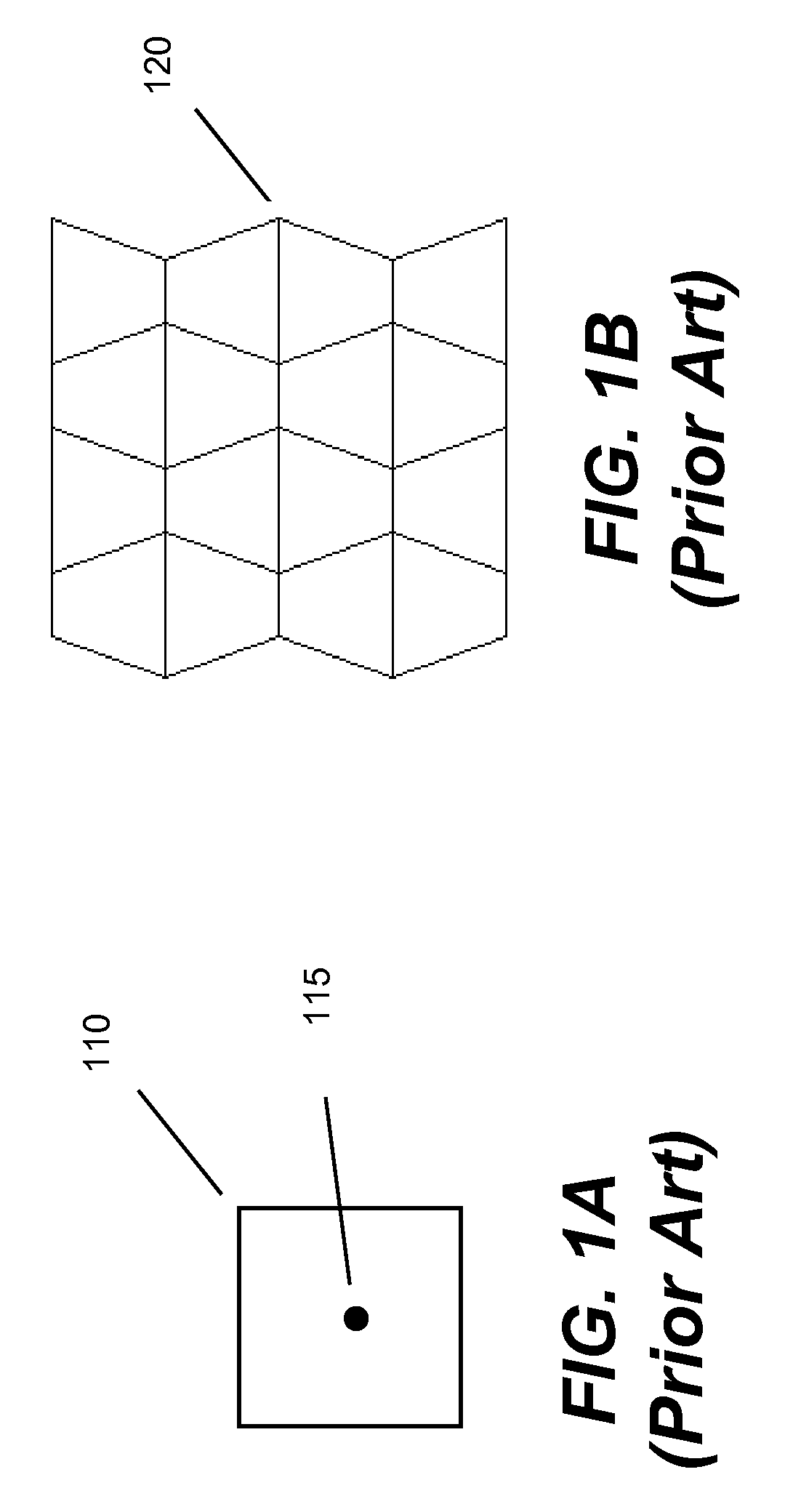
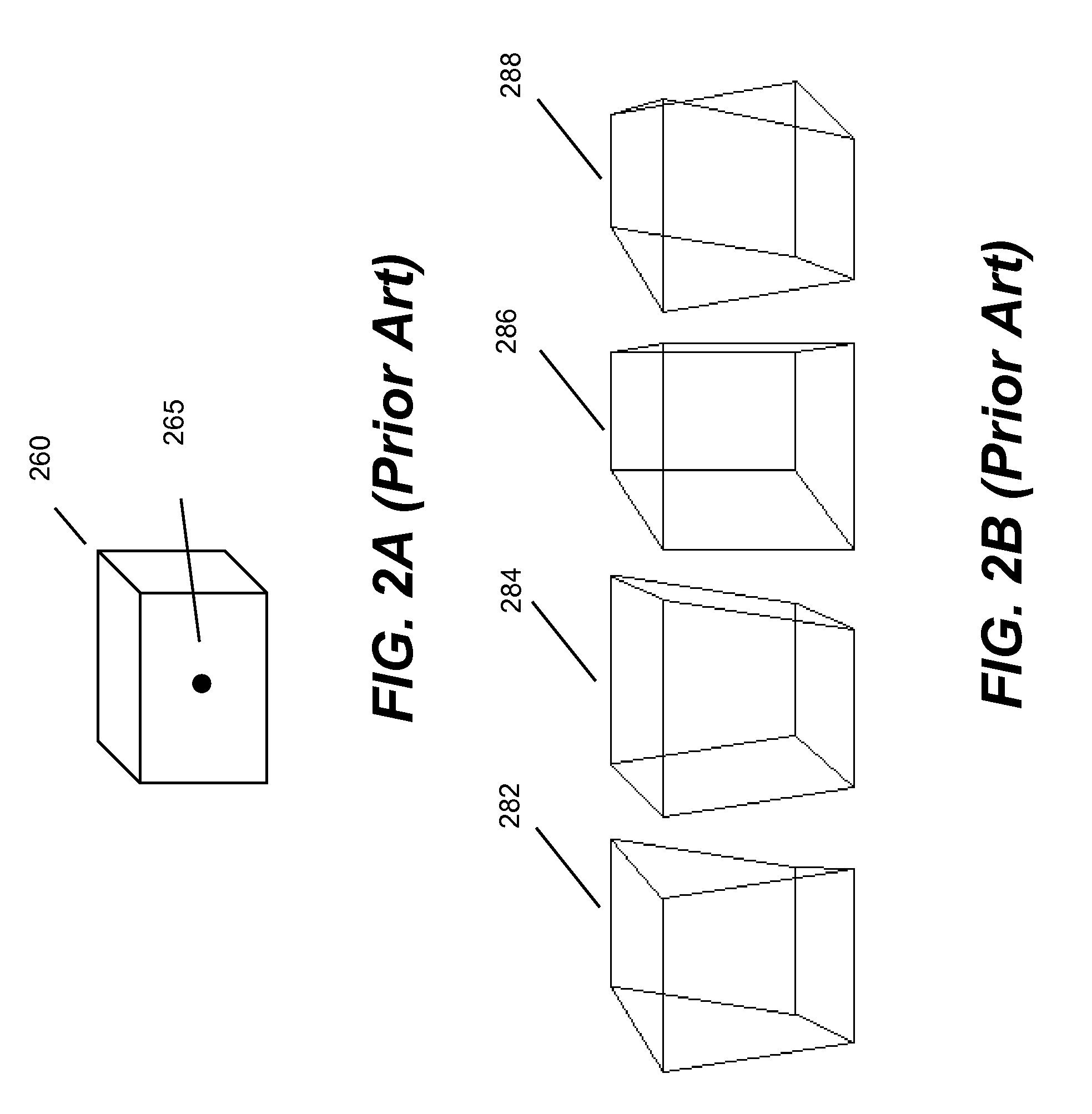
The disadvantage to numerical integration with only one integration point is that some modes of deformation do not contribute to the strain or stress field at the integration point.
Otherwise, the deformation due to these zero-energy modes may grow too large and dominate the solution.
This nonlinearity in the stiffness can cause residual hourglass deformation to remain in an element after some load is applied to the element and then removed.
Because the tire is skidding, we would also see frictional forces cause shear deformation of the element.
However, after a few rotations of the tire, we observed the brick elements of the tread failing to spring back to their undeformed geometries.

Method used


Image

  • Method and system for controlling hourglass deformations of solid elements in finite element analysis
  • Method and system for controlling hourglass deformations of solid elements in finite element analysis
  • Method and system for controlling hourglass deformations of solid elements in finite element analysis

Examples


Embodiment Construction

[0032]In the following description, numerous specific details are set forth in order to provide a thorough understanding of the present invention. However, it will become obvious to those skilled in the art that the present invention may be practiced without these specific details. The descriptions and representations herein are the common means used by those experienced or skilled in the art to most effectively convey the substance of their work to others skilled in the art. In other instances, well-known methods, procedures, components, and circuitry have not been described in detail to avoid unnecessarily obscuring aspects of the present invention.

[0033]Reference herein to “one embodiment” or “an embodiment” means that a particular feature, structure, or characteristic described in connection with the embodiment can be included in at least one embodiment of the invention. The appearances of the phrase “in one embodiment” in various places in the specification are not necessarily ...


PUM


Abstract

Hourglass deformations due to zero-energy or hourglass modes in rank-deficient solid elements must be effectively controlled, or the deformations may grow large and produce an unrealistic deformed geometry. Traditional methods of hourglass control allow error to accumulate by measuring hourglass deformation with incremental terms throughout a solution, which may produce inaccurate results due to unrealistic hourglass deformations. The present invention discloses a new method to control hourglass deformation without any incremental accumulations. Instead the nodal forces to resist hourglass deformations are calculated basing on the initial nodal coordinates and current nodal coordinates at each cycle. The present invention is implemented in a finite element software product.

Description

BACKGROUND OF THE INVENTION[0001]1. Field of the Invention[0002]The present invention generally relates to method, system and software product used in structural design and analysis using finite element analysis, more particularly to control zero-energy hourglass mode deformations of solid elements in finite element analysis.[0003]2. Description of the Related Art[0004]Finite element analysis (FEA) is a computerized method widely used in industry to model and solve engineering problems relating to complex systems. FEA derives its name from the manner in which the geometry of the object under consideration is specified. With the advent of the modern digital computer, FEA has been implemented as FEA software. FEA software can be classified into two general types, implicit FEA software and explicit FEA software. Implicit FEA software uses an implicit equation solver to solve a system of coupled linear equations. Such software is generally used to simulate static or quasi-static problem...

Claims


Application Information

Patent Timeline
Patent Type & Authority Patents(United States)
IPC IPC(8): G06F17/10
CPCG06F17/5018G06F30/23
Inventor BINDEMAN, LEE
Owner ANSYS
Why Eureka
Try Eureka