
Rotary punching apparatus

a rotary punching and rotary technology, applied in the field of rotary punching apparatuses, can solve the problems of limited punching position of sheets, uneven surface of sheets, and inability to insert sheets through coupling parts,

Inactive Publication Date: 2008-07-01
KIM OK HWAN +1
View PDF9 Cites 6 Cited by
  • Summary
  • Abstract
  • Description
  • Claims
  • Application Information

AI Technical Summary

Benefits of technology

[0011]Example embodiments of the present invention provide a rotary punching apparatus configured to freely punch on a desired position without regard to the punched position on a sheet as an object of a punching process, and enable a shape on the sheet to have the continuity.

Problems solved by technology

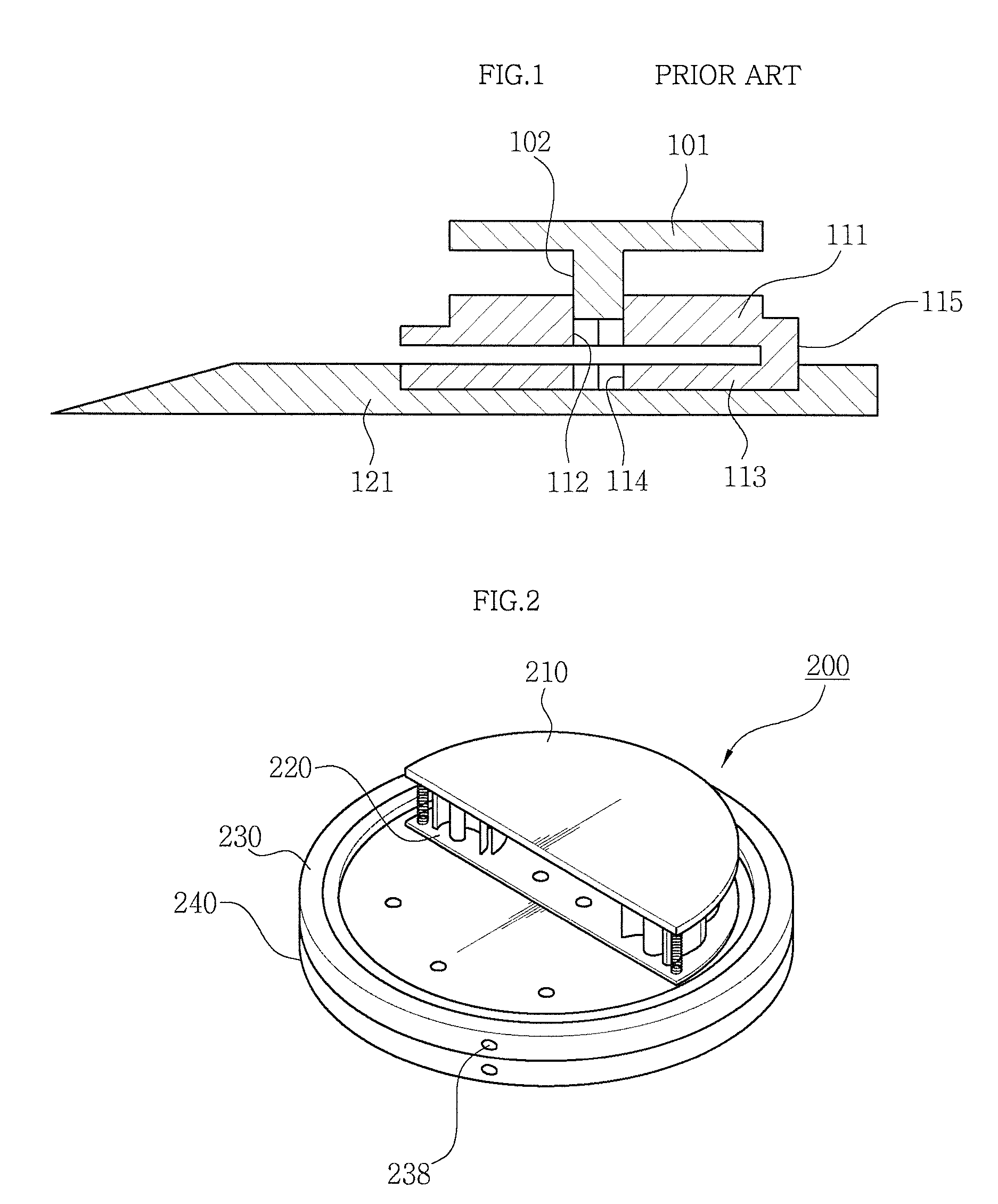
However, when the sheet is inserted into the conventional punching apparatus as described above, the sheet cannot be inserted by passing through the coupling part 115.
Accordingly, because the insertion of the sheet is limited by the coupling part 115, it has a problem that the punching position of the sheet is limited and punched to a boundary.
Further, it has a problem that a surface of the punched sheet is uneven, in case of punching the sheet by the punching blade and the punching hole, even though the upper jig and the lower jig are aligned by the coupling part.

Method used


Image

  • Rotary punching apparatus
  • Rotary punching apparatus
  • Rotary punching apparatus

Examples


second embodiment

[0070]FIG. 6 is a plan view illustrating a rotary punching apparatus according to the present invention.

[0071]Referring to FIG. 6, the fixing body 238a may be seated to the fixing groove 231c of the upper rotation plate 231 through its own elastic restoration force by being composed of an elastic piece 238a′ which is formed with the upper plate 230 in a body.

[0072]Further, though this is not illustrated in drawings, in case that the punching member (not shown) is formed in a fan shape at an angle of 30°˜60°, the shape of the upper jig and the lower jig which are engaged with the punching member is also the same shape as the punching member and is attached and detached to / from the seating hole of the rotation plate, so that the pattern of various shapes can be only punched by replacing the upper jig and the lower jig, without replacing the plate.

[0073]Hereinafter, an operation state of the rotary punching apparatus according to the present invention will be described in detail with r...


PUM

PropertyMeasurementUnit
angleaaaaaaaaaa
shapeaaaaaaaaaa
magnetic forceaaaaaaaaaa

Abstract

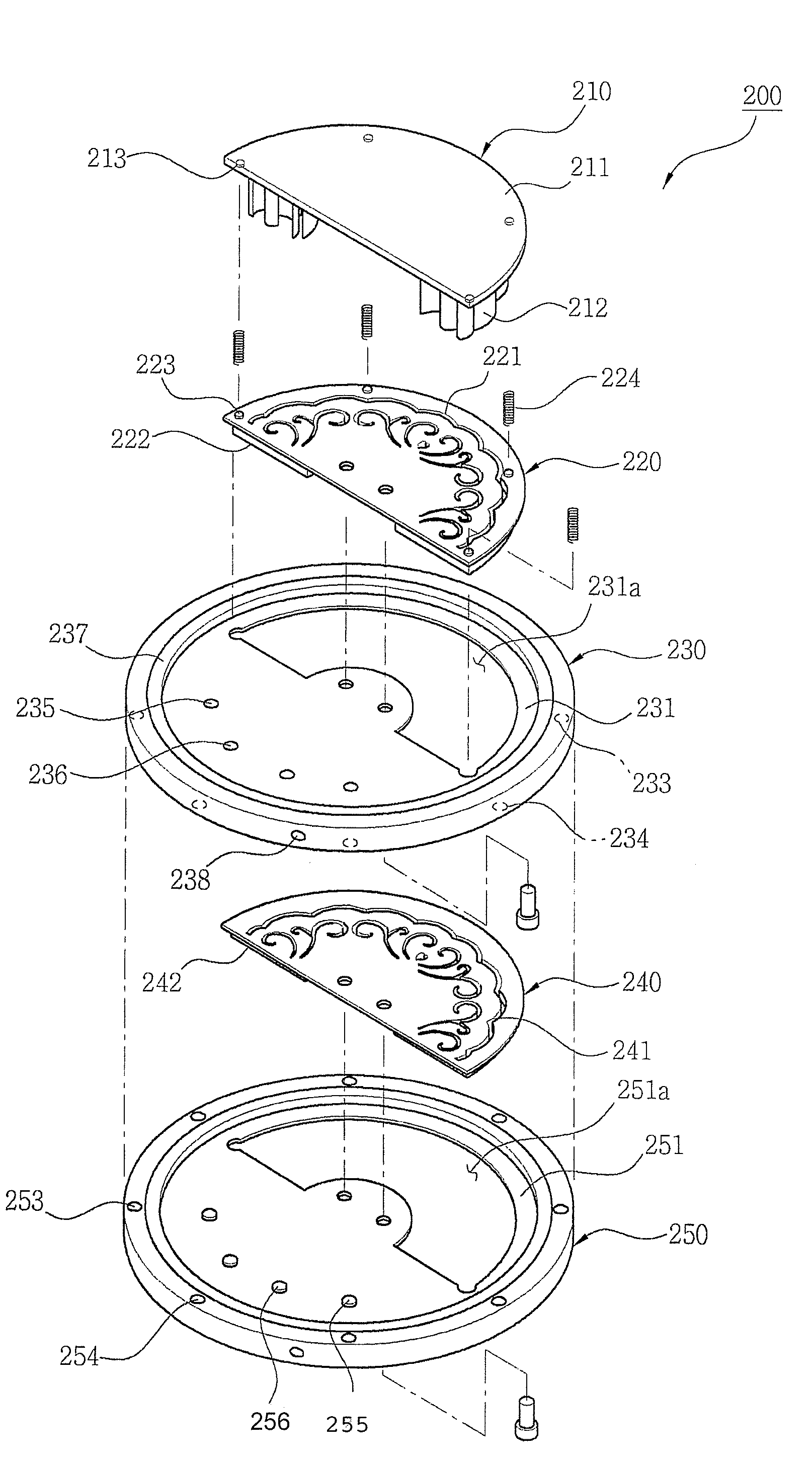
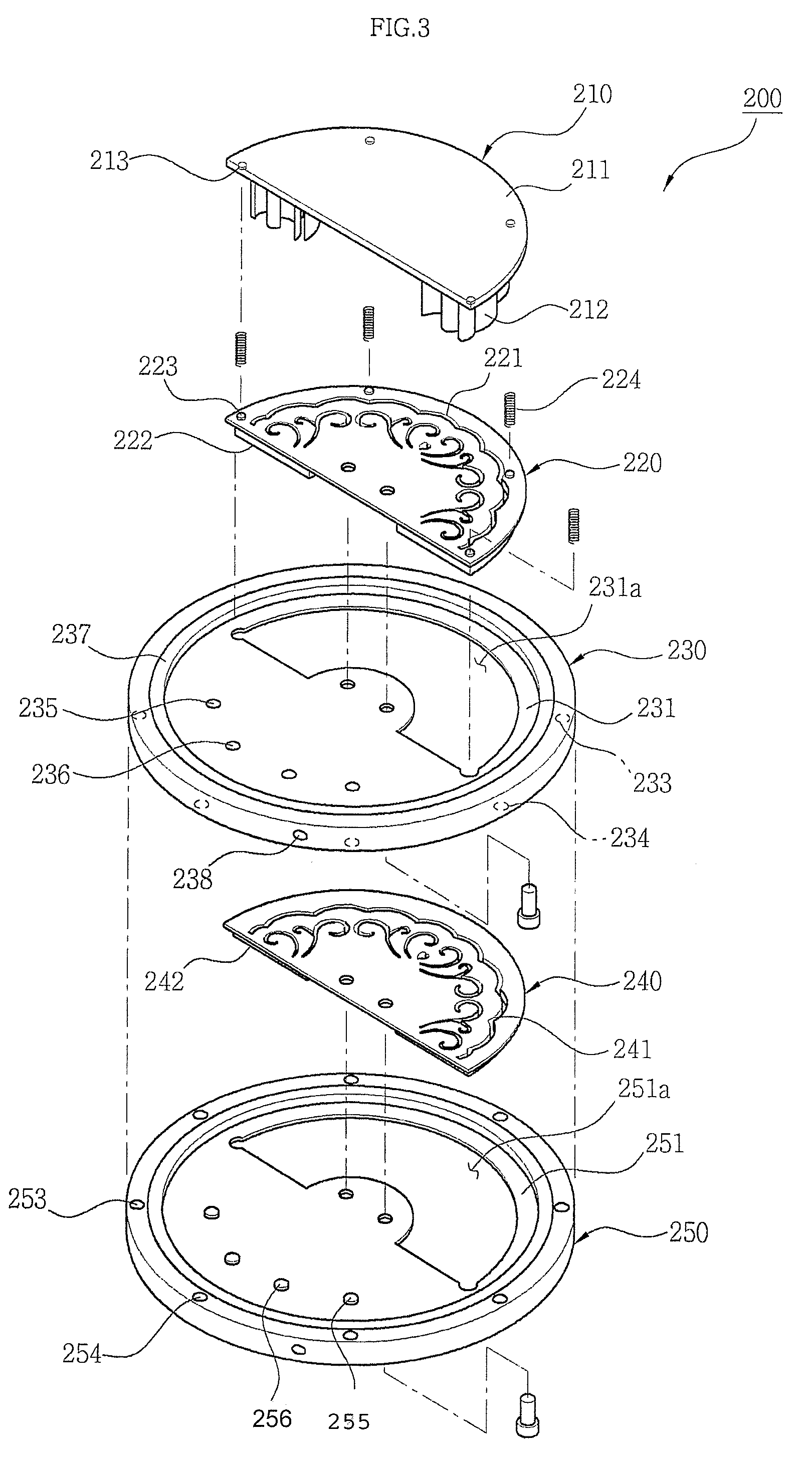
A rotary punching apparatus includes: an upper rotation plate provided with punching member on which punching blade having a pattern of a specific shape is formed, and an upper jig which support elastically the punching member and forms a guide hole in the same shape as the pattern; an upper plate configured to enable the upper rotation plate to be rotated; a lower rotation plate including lower jig on which a punching hole in the same shape as the pattern is formed; and lower plate configured to enable the lower rotation plate to be rotated.

Description

CROSS REFERENCE TO RELATED APPLICATION[0001]The present application claims priority to Korean Patent Application No. 10-2005-0062343 filed on Jul. 11, 2005, Korean Patent Application No. 10-2005-0099012 filed on Oct. 20, 20005 and Korean Patent Application No. 10-2005-0099013 filed on Oct. 20, 20005, all of which are incorporated herein by reference.BACKGROUND[0002]1. Field of the Invention[0003]Example embodiments of the present invention relates in general to the field of a rotary punching apparatus, and more specifically to a rotary punching apparatus which can perform punching on a desired position without regard to the punching position on a sheet which becomes an object of punching and simultaneously enable a shape on the sheet to have the continuity and a uniformly punched surface.[0004]2. Description of the Related Art[0005]In general, a punching apparatus is an apparatus for punching a predetermined part such as pictures, cards, letter papers and the like (hereinafter refer...

Claims


Application Information

Patent Timeline
Patent Type & Authority Patents(United States)
IPC IPC(8): B26F1/04
CPCB26D7/2628B26F1/36B26D3/10B26D2007/0056B26D2007/0087B26F1/46B26F1/14B26F1/32B26F1/02Y10T83/943Y10T83/8831Y10T83/8841Y10T83/944Y10T83/8785
Inventor KIM, OK-HWANLEE, SANG-HO
Owner KIM OK HWAN
Learn More