
System for measuring an airflow angle at the wingtip of an aircraft

a technology for aircraft wings and wingtips, which is applied in the direction of navigation instruments, golf clubs, instruments, etc., to achieve the effect of reducing or minimizing the problems of turning the aircraft and/or yawing

Inactive Publication Date: 2008-07-08
SAFE FLIGHT INSTR
View PDF9 Cites 2 Cited by
  • Summary
  • Abstract
  • Description
  • Claims
  • Application Information

AI Technical Summary

Benefits of technology

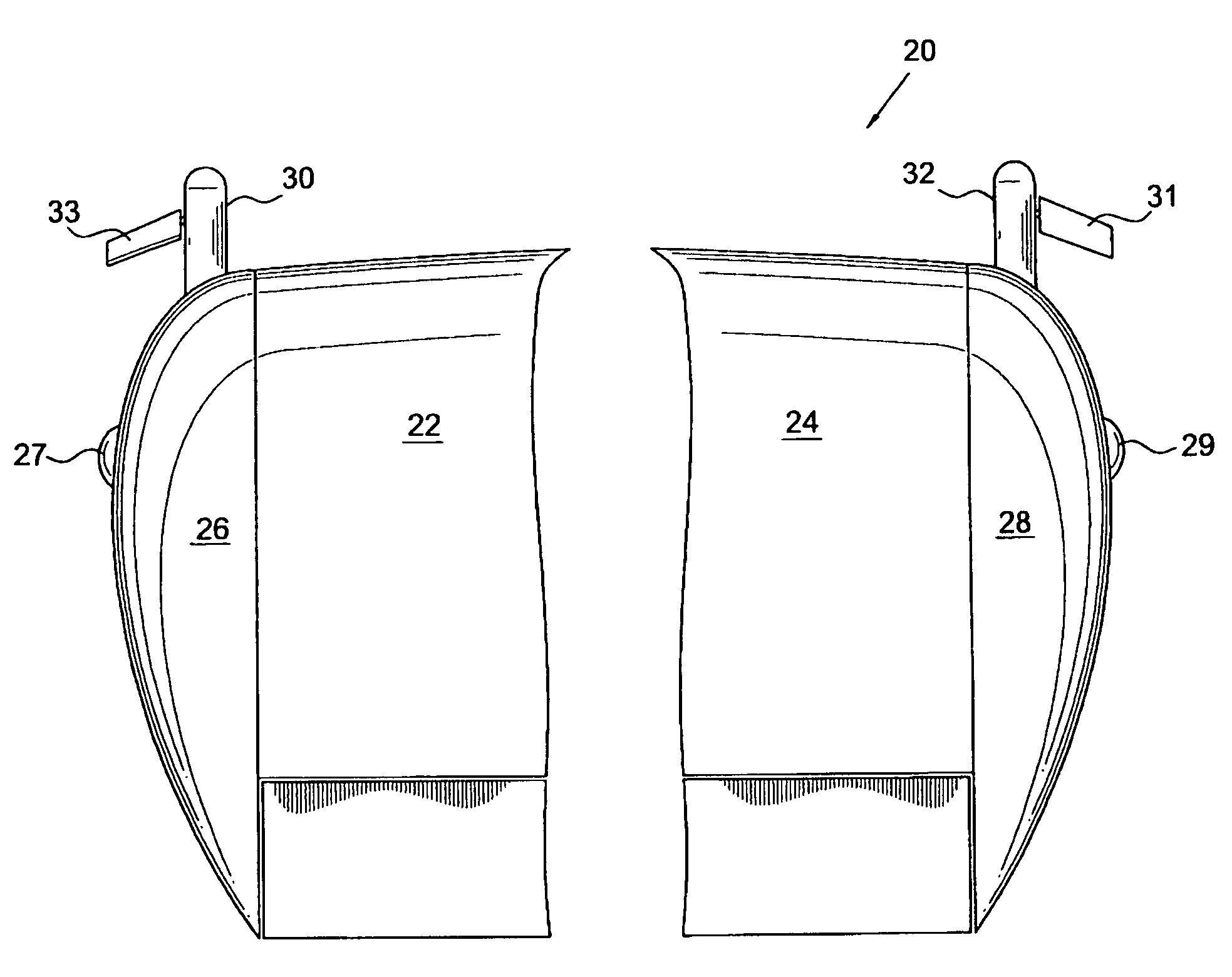
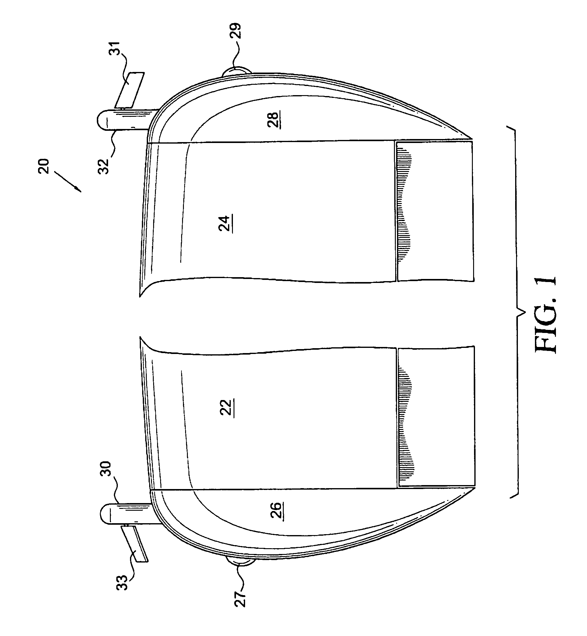
[0008]In essence, the present invention contemplates a vortex angle system which includes a sensor such as a vane and means for generating a signal responsive to the position of the vane. In this invention, the sensor is located on or immediately adjacent to and forward of a wingtip as opposed to being mounted on an aircraft's fuselage or on an inward portion of a wing. It is presently believed that locating the sensor forward of the wingtip will reduce or minimize problems associated with turning the aircraft and / or yaw due to a potentially inaccurate measurement.

Problems solved by technology

It is presently believed that locating the sensor forward of the wingtip will reduce or minimize problems associated with turning the aircraft and / or yaw due to a potentially inaccurate measurement.

Method used


Image

  • System for measuring an airflow angle at the wingtip of an aircraft
  • System for measuring an airflow angle at the wingtip of an aircraft
  • System for measuring an airflow angle at the wingtip of an aircraft

Examples


Embodiment Construction

[0015]As a plane flies through the air, the wings must have a certain minimum pitch relative to the direction of flight in order to create the lift for supporting the weight of the plane. The pitch or angle between the wing centerline and the direction of the flight is known as the angle of attack. Since a wing develops greater lift at higher speeds, the necessary angle of attack at higher speeds is less than at lower speeds. Therefore, there is an inverse relationship between the angle of attack and airspeed for any particular plane.

[0016]Angle of attack becomes critically important at slow speeds when the aircraft is relatively close to the ground since every airplane has a certain angle of attack beyond which it goes into a stall. Every plane has a corresponding stall speed that will vary depending on loading, turning and banking conditions at the stall angle. However, the angle of attack provides a consistent indication of the aircraft's lift characteristics regardless of the pa...


PUM


Abstract

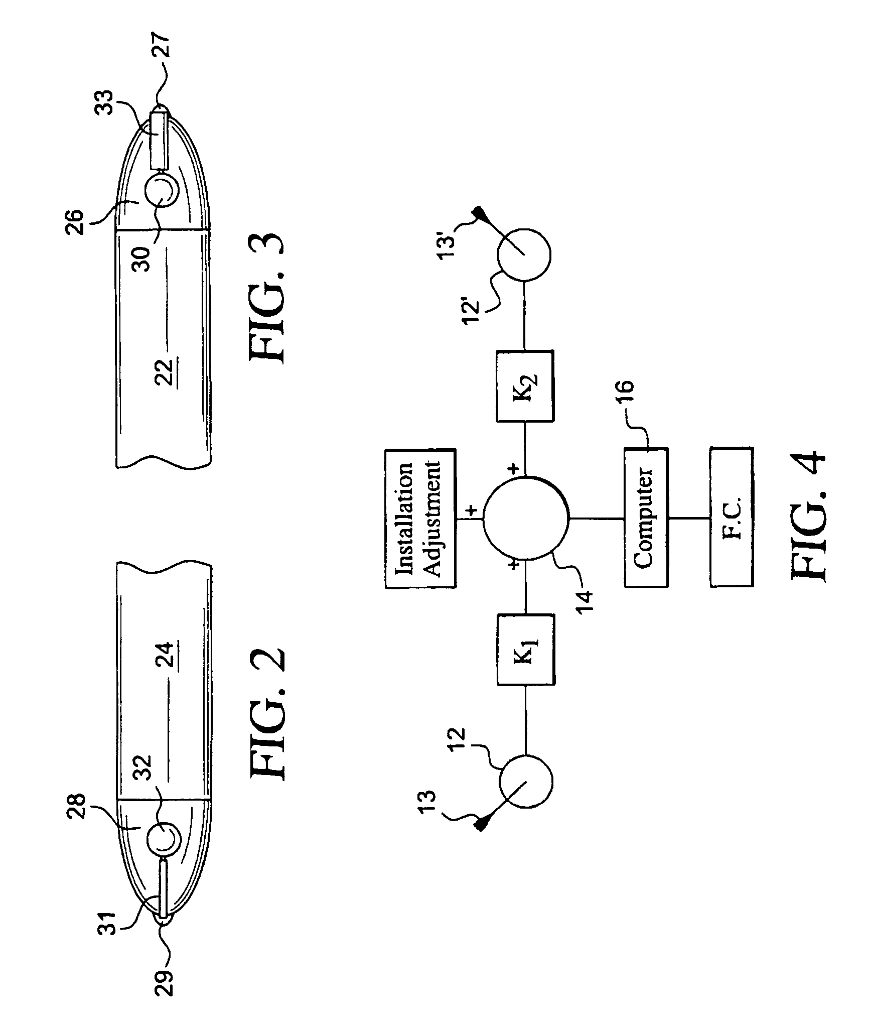
A vortex angle system includes one or more vortex angle sensors disposed on one or more wingtips of an aircraft. A summing circuit and computer compare signals from each sensor to provide a signal, which is indicative of the average vortex angle of the aircraft.

Description

FIELD OF THE INVENTION[0001]This invention relates to a system for measuring the airflow angle at the wingtip of an aircraft and more particularly to a device for measuring the vortex angle of an aircraft.BACKGROUND FOR THE INVENTION[0002]Modern commercial aircraft typically include a stall warning system which is triggered by the angle of attack of the aircraft as determined by an angle of attack vane. Such aircraft also include an integrated airspeed control command and display system which aids a pilot during take-off, climb out, let down, approach, landing and go-around maneuvers. Such integrated systems are also based on various parameters relating to flight conditions including the aircraft's angle of attack as determined by an angle of attack vane or the like.[0003]It is customary to locate the angle of attack vane on the sides of an aircraft's fuselage. However, these side mountings may lead to problems when the aircraft is in a banked turn or flown in a yawed flight. Under ...

Claims


Application Information

Patent Timeline
Patent Type & Authority Patents(United States)
IPC IPC(8): G01P13/00
CPCB64D43/02
Inventor GREENE, LEONARD M.
Owner SAFE FLIGHT INSTR
Learn More